 EDM Setup
Introduction
The EDM Setup page gives you access to Parameters and Output options for the job.
Navigation
To access the Current Settings Job dialog box:
- In the CAM Tree, right-click
 Wire
EDM Job, and click Current Settings. With the Current Settings dialog open, click EDM Setup in the tree on the left.
Wire
EDM Job, and click Current Settings. With the Current Settings dialog open, click EDM Setup in the tree on the left.
 EDM Setup
Parameters
- Wire Diameter - is the diameter of the wire for the program. Click the arrow and select the appropriate wire size.
- Maximum Taper Angle - is the maximum amount of taper, in degrees, that can be output by the software for tapered features. Type the maximum value supported by your machine in this box.
- Maximum Taper with Land - determines the maximum amount of taper, in degrees, that the software will output for taper with land features. Type the maximum value supported by your machine in this box.
- Upper Guide Location - sets the distance of the upper guide as an incremental value from the Top of Stock for the job.
- Lower Guide Location - set the distance of the lower guide as an incremental value from the bottom of the stock for the job.
-
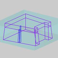
Taper Display Extend
This option determines the Job default setting in the Wire EDM Wizard for creating Land and Taper operations.
![]() Select the check box to extend the graphical display of the wirepath for
each Land and Taper operation to the vertical extents of the feature.
Select the check box to extend the graphical display of the wirepath for
each Land and Taper operation to the vertical extents of the feature.
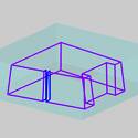
![]() Clear the check box to turn off the extended taper display. The wirepath
for each operation displays only in the areas they cut as if looking at
the finished part or feature.
Clear the check box to turn off the extended taper display. The wirepath
for each operation displays only in the areas they cut as if looking at
the finished part or feature.
Output
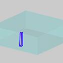
- Use Auto Threading
![]() Select the check box to allow the software to output auto threading codes
for machines equipped with an auto threader.
Select the check box to allow the software to output auto threading codes
for machines equipped with an auto threader.
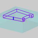
![]() Clear the check box to not allow auto threading code output.
Clear the check box to not allow auto threading code output.
-
AWT Minimum Distance - Any distance greater than this value will cause the posting engine to cut the wire and rethread the wire at the start of the next pass. Also, if the length of the lead-in/out are shorter than this distance, a lead length of this value will be applied.
- Output Start Hole Program
![]() Select the check box to output a separate start hole program in addition
to the normal NC program output. You must have the proper Hole Post processor
defined on the posting page.
Select the check box to output a separate start hole program in addition
to the normal NC program output. You must have the proper Hole Post processor
defined on the posting page.
![]() Clear the check box when not outputting a start hole program.
Clear the check box when not outputting a start hole program.