The Wire EDM Wizard Feature Settings
Introduction
The second step of the Wire EDM Wizard is to define the Feature Parameters. These parameters define the guide heights, feature processing, glue stop options, and taper options that are applied to all operations in the feature. All of the parameters found in the Feature dialog box are explained in this topic.
 Feature
Feature Parameters
- Stock Thickness - is an informational display to show the stock thickness defined for the job.
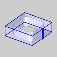
- Upper Guide - sets the vertical distance of the upper guide as an incremental value from the top of stock. Type a positive value.
- Lower Guide - sets the vertical distance of the lower guide as an incremental value from (below) the bottom of the stock. Type a positive value.
Note: Most modern controllers do not require the output of coordinates from the guide positions as this is handled at the control. In most cases, these values are only utilized for simulation purposes.
Process As
The following options only display for 2 Axis Open and 4 Axis Open features.
- Punch - (or outside) sets the feature to be processed as an outside feature. This makes all of the appropriate parameters for Outside feature types available in the Wire EDM Wizard.
- Die - (or inside) sets the feature to be processed as an inside feature. This makes all of the appropriate parameters for Inside feature types available in the Wire EDM Wizard.
Glue Stop Options
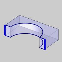
The Glue Stop Options are used to define a stop along the feature in order to leave a tab that holds the part in place until the Tab Cut operation is performed. The following options are used to determine the use of glue stops.
- No Glue Stop - creates the feature without using a glue stop. All rough and skim operations cut the entire feature.
Note: When you select No Glue Stop, the Tab Cut operation is no longer available in the Machining Strategy of the Wire EDM Wizard. (The Tab Cut operation is removed from Templates, Current Operations, and Available Operations, in the wizard, until one of the Use Glue Stop options is selected).
- Use Glue Stop with Leads
- creates the feature using a glue stop with lead moves into and out
of the profile. The glue stop is always applied to the end of the
chain (defined by the Start Point), and it is cut using a Tab Cut
operation.
- Use Glue Stop without Leads
- creates the feature using a glue stop where the wire stops on the
profile instead of creating lead moves. This glue stop type is cut
by a Tab Cut operation in which the lead-out move of the previous
operation and the lead-in move of the Tab Cut operation are removed
to allow the operation to stop on the feature profile. This Glue Stop
Option is only available for inside feature types (or Open feature
types set to Die).
- Stop Distance - when using a glue stop, this determines the length of the tab (remaining material) from the end of the feature as defined by the feature start point. This value must be equal or less than one-half (50 percent) of the length of the feature profile.
Note: The Parameters page of the Tab Cut operation (for Outside features or Open features set to Punch) contains options to define a portion of the Glue Stop as a Knockout, which leaves a portion of the Glue Stop in order to allow the machine operator to knockout the unused portion of the part, for example, with a hammer or mallet.
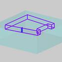
Taper Settings
The Taper Settings display for 2 Axis Wire EDM features only. The following parameters are used to determine the type and amount of taper applied to the feature.
No Taper
The None option does not apply any taper to the feature.
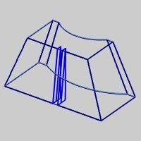
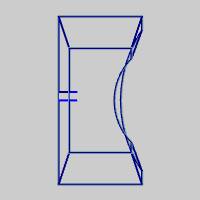
Taper
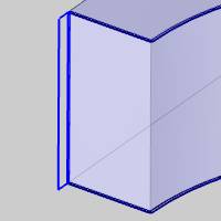
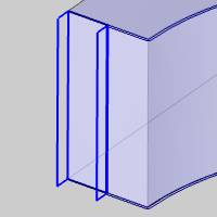
The Taper option applies a fixed taper to the feature by the specified Taper Angle.
-
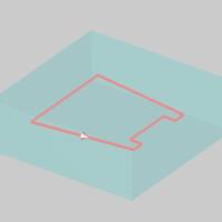
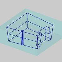
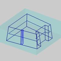
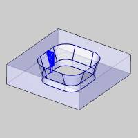
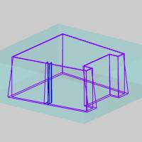
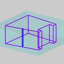
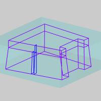
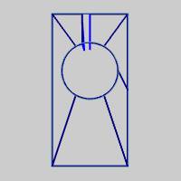
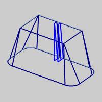
Taper Angle (-) Left (+) Right - determines the amount of taper applied to the feature in reference to the chain direction (defined using Modify Start Point). Positive values apply the taper to the right of the cut direction, and negative values apply the taper to the left of the cut direction.
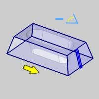
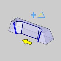
Note that the two previous images use Taper from Bottom as explained next.
-
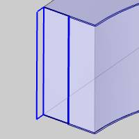
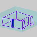
Taper from Bottom
![]() Select the check box to apply the Taper Angle from the bottom of the feature.
The selected geometry is treated as the bottom of the feature.
Select the check box to apply the Taper Angle from the bottom of the feature.
The selected geometry is treated as the bottom of the feature.
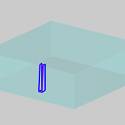
![]() Clear the check box to apply the Taper Angle from the top of the feature.
The selected geometry is treated as the top of the feature.
Clear the check box to apply the Taper Angle from the top of the feature.
The selected geometry is treated as the top of the feature.
Tip: The Taper from Bottom option allows you to select the 2-axis geometry from any Z-height and apply the taper (and the geometry) where you need it, from the top of the feature or from the bottom.
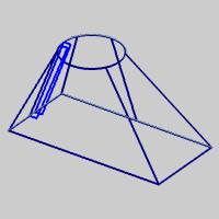
Land and Taper
The Land and Taper option applies a fixed taper cut in addition to a land cut which contains no taper. Typically, the Rough Cut operation cuts the taper portion of the feature, and the Skim Cut operation cuts the land or non-tapered portion of the feature. This option is used to create a relief cut above or below the land portion using the following options.
Note: Land and Taper is only available for 2 Axis Inside features and 2 Axis Open features set to Process As Die (inside).
-
Taper Angle - determines the amount of taper applied to the taper portion of the feature. For 2 Axis Inside features, the value must be positive and the software automatically creates the proper taper for the feature. For 2 Axis Open features (set to Die) you define a positive or negative taper angle based on the chain direction of the feature.
-
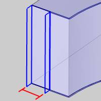
Land Height - sets the vertical distance of the land portion for Land and Taper features.
-
Land On Top
![]() Select this check
box to apply the land to the top of the feature.
Select this check
box to apply the land to the top of the feature.
![]() Clear this check
box to apply the land to the bottom of the feature.
Clear this check
box to apply the land to the bottom of the feature.
Taper Display Settings
-
Use Job Setting
![]() Select the check box to use the Taper Display Extend setting that is selected
in Current Settings.
Select the check box to use the Taper Display Extend setting that is selected
in Current Settings.
![]() Clear the check box to set the Taper Display Extend option in the wizard
as follows. (This allows you to override the job setting.)
Clear the check box to set the Taper Display Extend option in the wizard
as follows. (This allows you to override the job setting.)
-
Taper Display Extend
![]() Select the check box to extend the graphical display of the wirepath for
each Land and Taper operation to the vertical extents of the feature.
Select the check box to extend the graphical display of the wirepath for
each Land and Taper operation to the vertical extents of the feature.
![]() Clear the check box to turn off the extended taper display. The wirepath
for each operation displays only in the areas they cut as if looking at
the finished part or feature.
Clear the check box to turn off the extended taper display. The wirepath
for each operation displays only in the areas they cut as if looking at
the finished part or feature.
Tip: In order to create Land and Taper features with a Tab Cut operation on both the land and taper parts of the feature, add two Tab Cut operations in the Machining Strategy of the wizard. In the Parameters pages of the Tab Cut operations, turn on Apply Taper for one operation and turn off Apply Taper for the other.
Sync Options
The Sync Options only display for 4 Axis Wire EDM features. These settings handle the synchronization of the Upper Guide and Lower Guide along the wirepath. These options can be used with or without selecting Sync Line geometry for the feature.
-
By Entity - uses the number of entities to define the transition between sync lines. The software attempts to match, one-to-one, each entity of the lower profile with each entity of the upper profile. This option is ideal when the number of entities in the upper profile is equal to the number of entities in the lower profile. The other Sync Options (and the Sync Line selection) are provided so that you don't have to create an equal number of entities in the upper and lower profiles.
-
By Proportion - the software creates the transition by calculating a proportion between the length of the upper profile and lower profile. The upper profile and lower profile are automatically separated into an equal number of segments and synced at the start and end of these segments.
-
By Closest - syncs the profile to the closest entity start or end point (of the other profile) to determine the transition.
Next Topic
After setting the Feature parameters, click Next>> to go to The Wire EDM Wizard Machining Strategy.