Geometry Selection
Introduction
This topic will explain geometry selection for the Wire EDM features, and will provide links to related topics.
Geometry Selection
The first step of any Wire EDM Wizard is to assign geometry for the feature. All operations in the feature are performed on the selected geometry. The Wire EDM features use wireframe geometry such as lines, arcs, splines, points, surfaces/solids, or the edges of solids/surfaces. When selecting surface geometry, all of the edges (holes, bosses, islands) are extracted from the solid and they are automatically projected to a flat plane (Top of Feature). Since 2 axis, and 4 axis features have different options, the Feature Geometry Picking dialog is slightly different for each.
2 Axis Feature
- Select Geometry - Clicking the Select Geometry
button launches the Feature Geometry Picking dialog, which is used to assign wireframe entities,
surfaces/solids, or surface/solid edges to the feature.
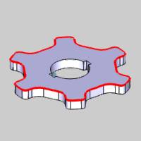
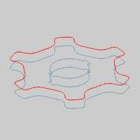
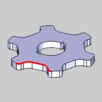
Feature Geometry Picking
Selected Geometry
|
|
|
| The list box will list the entities currently selected for the function. | |
Start Point & Direction
This group allows you to control the full chains which were formed from the selected geometry. You can control the direction of the chains, and the location of the start point on the chains.
Start Point
This group allows you to set the start point using the following buttons:
- Start of Chain - When a closed chain is selected, this option sets the start point to the first selected entity in the chain.
- Start of the Longest Entity - When a closed chain is selected, this option sets the start point to the start of the longest entity in the chain.
- Middle of the Longest Entity - When a closed chain is selected, this option sets the start point to the middle of the longest entity in the chain.
Note: When open chains are selected, you can only start from one end, or the other. To change the start point on open chains, use the reverse options for the Profile Chains list box below.
- Closest to Points
 - Points are not taken into consideration for the start point.
  - Gives you access to the Selected Points list seen below. This allows you to select points from the graphics area to use for the start points. You may also use the Apply to Operation Leads below to utilize these points for the lead location.
Selected Points
|
|
|
| The list box will list the entities currently selected for the function. | |
- Apply to Operation Leads - The leads Select Point, and Point Blend allow you to define a point to use for the start position of the lead by entering the coordinates manually, or picking a point from the graphics area. Utilizing this option will ensure that when one of those leads are used, the points selected in the Selected Points list above will be utilized automatically.
Profile Chains
|
|
|
| This list box will show the chains currently selected for the function. | |
Stop Points - this list allows you to add points from the graphics area to define as Stop Points for the feature. When the Apply Stop Points option is selected in the Stop Settings group of the Parameter page in a particular operation, these are the points that will be utilized. The Apply Stop Points option is active by default.
|
|
|
| The list box will list the entities currently selected for the function. | |
4 Axis Feature
Clicking any of the buttons below launches the Feature Geometry Picking dialog, which is used to assign wireframe entities, surfaces/solids, or surface/solid edges to the feature.
- Select Upper Profile
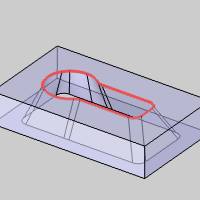
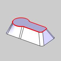
- Select Lower Profile
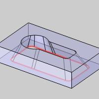
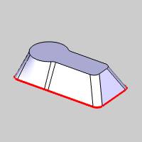
- Select Sync Lines
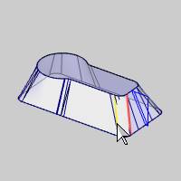
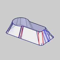
Note: The Feature settings of the Wire EDM Wizard contain the Syncing Options that are used with or without selecting geometry as Sync Lines.
Feature Geometry Picking
Upper Geometry
|
|
|
| The list box will list the entities currently selected for the function. | |
Lower Geometry
|
|
|
| The list box will list the entities currently selected for the function. | |
Start Point & Direction
This group allows you to control the full chains which were formed from the selected geometry. You can control the direction of the chains, and the location of the start point on the chains.
Start Point
This group allows you to set the start point using the following buttons:
- Start of Chain - When a closed chain is selected, this option sets the start point to the first selected entity in the chain.
- Start of the Longest Entity - When a closed chain is selected, this option sets the start point to the start of the longest entity in the chain.
- Middle of the Longest Entity - When a closed chain is selected, this option sets the start point to the middle of the longest entity in the chain.
Note: When open chains are selected, you can only start from one end, or the other. To change the start point on open chains, use the reverse options for the Profile Chains list box below.
- Closest to Points
 - Points are not taken into consideration for the start point.
  - Gives you access to the Selected Points list seen below. This allows you to select points from the graphics area to use for the start points. You may also use the Apply to Operation Leads below to utilize these points for the lead location.
Selected Points
|
|
|
| The list box will list the entities currently selected for the function. | |
- Apply to Operation Leads - The leads Select Point, and Point Blend allow you to define a point to use for the start position of the lead by entering the coordinates manually, or picking a point from the graphics area. Utilizing this option will ensure that when one of those leads are used, the points selected in the Selected Points list above will be utilized automatically.
Upper Profile Chain
|
|
|
| This list box will show the chains currently selected for the function. | |
Lower Profile Chain
|
|
|
| This list box will show the chains currently selected for the function. | |
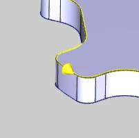
The chains direction can be seen in the graphics area as in the image below.
Sync Lines - this list allows you to add geometry from the graphics area to define as Sync Lines for the feature, as seen in the images below. The Sync Lines assure that the wire will share the same alignment when it reaches the location of the Sync Lines.
|
|
|
| The list box will list the entities currently selected for the function. | |
Stop Points - this list allows you to add points from the graphics area to define as Stop Points for the feature. When the Apply Stop Points option is selected in the Stop Settings group of the Parameter page in a particular operation, these are the points that will be utilized. The Apply Stop Points option is active by default.
|
|
|
| The list box will list the entities currently selected for the function. | |
OK - confirms the geometry and closes the Feature Geometry Picking manager.
Cancel - cancels geometry selection and closes the Feature Geometry Picking manager.
Next Topic
After selecting geometry and making any necessary changes, click Next>> to go to The Mill 2 Axis Wizard Feature Settings.
 (Delete All)
- removes all entities from the list.