Retract Tool Along tool Axis - Advanced Options
Introduction
This collision control retracts the tool along its tool axis when a collision is detected.
Advanced Options
Once Retract Tool is selected, click Advanced to open the Advanced Options for Retracting Tool Along Tool Axis dialog box with the following options. Some or all of the following options display based on the selected retract direction (for example, Along Tool Axis or Along User Defined Direction).
- Drop Tool Down
Wherever Needed
 Select this check
box to project the toolpath from the drive surface to the check surface.
Select this check
box to project the toolpath from the drive surface to the check surface. Clear the check box when not projecting the toolpath.
Note: Because all of the remaining advanced options control the tool projection, they are not available until the Project Tool On Direction Where Needed check box is selected.
- Move
Tool Outwards Wherever Needed
Select the check box to define a Maximum Outward Distance to
limit the toolpath projection. Clear this check
box when not defining a maximum outward projection distance.- Max.
Outward Distance - type the maximum distance value for
the outward projection distance.
- Max.
Outward Distance - type the maximum distance value for
the outward projection distance.
- Project
Tool Inward Wherever Needed
Select this check
box to define a Maximum Inward Distance to limit the toolpath projection. Clear this check
box when not defining a maximum inward projection distance.- Max.
Inward Distance - type the maximum distance value for the
inward projection of the toolpath.
- Max.
Inward Distance - type the maximum distance value for the
inward projection of the toolpath.
- Remove Areas Where
Project Tool Fails
Select this check
box to trim areas that do not touch the check surface and/or are beyond
the maximum inward or outward distance.
Clear the check box to not trim the toolpath projection. - Reverse
Select this check
box to reverse the projection direction. Clear this check
box to use the original projection direction. - Remove
Areas Where Tool Drop Fails - is only available when the Drop
Tool Down Wherever Needed check box is selected. Select the check box to remove the areas where the projected
toolpath does not touch the check surface/face.
Clear the check box to not remove any of the projected toolpath.
- Smooth Retracts
Select the check box to smoothen the retract movement based on the specified Smooth Distance value. The distance value creates an angled retract move instead of being vertical, as shown in the dialog box images.
Clear the check box to turn off smooth retracts.
Examples
Example 1
- This image shows a situation with
a tool machining a flat surface (blue) and having a collision with
a check face (red).
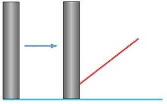
- At the area of collision, the tool
retracts along its tool axis.
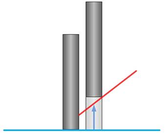
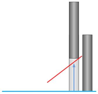
- After the collision, the tool plunges
back down to the drive surface.
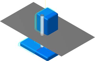
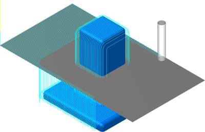
Example 2
- In the next example the purpose is
to create parallel cuts on all faces of the following part.
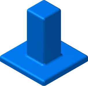
- Next a flat surface is created for
use as a drive surface.
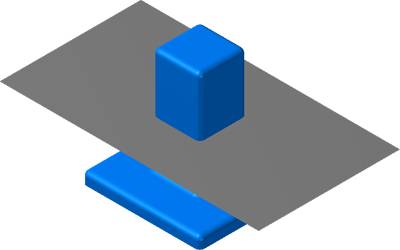
- The toolpath is generated on the drive
surface.
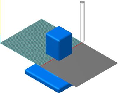
-
The previous image shows that the
toolpath is colliding with the part. The gouge check strategy Retract
Tool Along Tool Axis is selected as shown next.
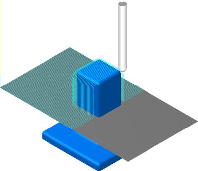
- The toolpath doesn't gouge the blue
faces, but it doesn't machine the floor faces either. The next step
is to select Drop Tool Down Wherever Needed. The result is shown in
the next image.
- The tool plunges through the grey
drive surface and reaches the lower faces of the part. Now, actually
all motions on the flat surface are not necessary. With Remove Areas
Where Tool Drop Fails selected, all unnecessary motion are deleted.