How to Create a Toolpath Pattern - 2D Rotate
Introduction
This tutorial explains how to create a toolpath pattern using the 2D Rotate option. The example provided shows how to pattern multiple features together and rotate the pattern around a point.
Example Part
The
Part 1) Pattern the Features
In the example file provided, two features are already created with pocketing operations. One feature cuts the closed pocket shape. The second feature cuts the open pocket shape on the outside of the part. The geometry used for the second feature is placed on a separate layer named Open Pocket Geometry. Instead of creating a pattern for each feature separately, the following steps are used to pattern both (or all) features contained in the Machine Setup.
-
In the
-
In the CAM Tree, right-click
 Machine Setup, point to Additional Functions, and click
Add Toolpath Pattern.
Machine Setup, point to Additional Functions, and click
Add Toolpath Pattern.
When you add a toolpath pattern to a Machine Setup, all features in the Machine Setup are patterned.
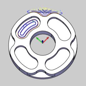
The features being patterned are shown next for reference. -
In the ToolpathPattern dialog box, click Rotate, and click Next>>.
-
In the Rotate group, in the Angle box, type 90.00.
This defines the amount of rotation applied to create each copy of the patterned features.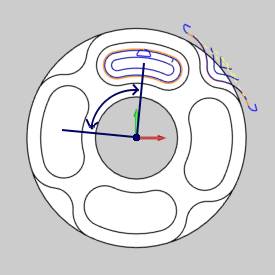
-
In the Copies box, set the value to 3.
This creates three patterned copies of the original features.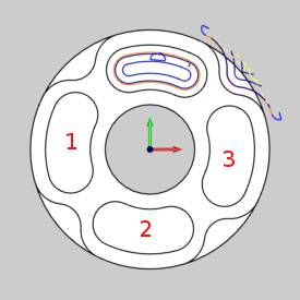
-
In the Rotation Axis group, make sure that the Origin values are set to X0 Y0.
This defines the center of rotation for the pattern based on the machining origin of the part (which is defined in the Machine Setup).
For this example, the machining origin is at the top and center of the part. -
At the bottom of the dialog box, click OK.
The toolpath pattern is automatically calculated.
The result is shown next.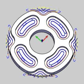
Part 2) Simulate the Program
-
To simulate the program, in the
 Simulation.
After simulating, the stock model appears as shown next.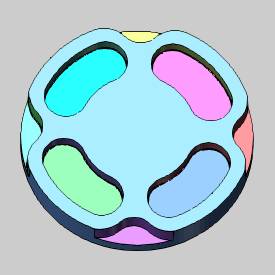
-
To close the simulation, in the
 Exit Simulation.
This concludes the tutorial.