Mill Turn Hole Drilling Example
Introduction
This topic provides an example of how to create Mill Hole features for Mill-Turn jobs in BobCAD-CAM. First, standard drilling is used to perform all face drilling, then cross drilling handles all X-axis drilling that points to center line (radial drilling), and finally, multiaxis drilling is used to machine all other holes in the model (holes that can't be machined with standard or cross drilling.)
Example File
The BobCAD part file for this tutorial is available for download at: http://bobcad.com/helpfiles. If you are connected to the Internet, you can click the link provided to download and save the Mill Turn Drilling Example 1 BBCD.zip file. After extracting the zip file, you can open the file to follow along with this example. In the example file provided, the job, stock, and machine setup are already defined.
Part 1) Create a Mill Hole Feature (Standard Drilling)
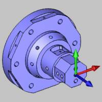
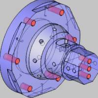
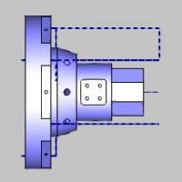
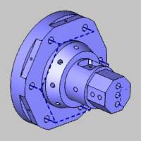
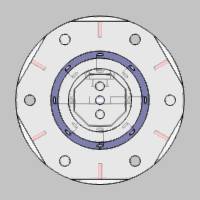
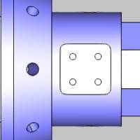
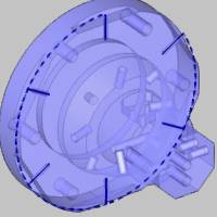
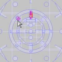
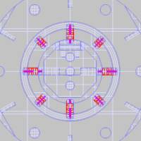
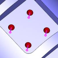
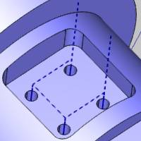
Standard drilling handles all holes in which the tool orientation is parallel to the main spindle direction, which is usually the Z-axis. For mill turn jobs, this is also known as face drilling. This is the first feature that we create for our mill turn part. The following image shows the part and machine setup location.
Set Drilling Type and Select Geometry
-
In the CAM Tree, right-click Machine Setup, point to Mill Features, and click Mill Drill Hole.
-
In the Mill Hole Wizard, click Select Geometry.
The Hole Geometry Selection Manager displays.
Notice the default drilling type is Standard Drill. -
For our standard drilling feature, we select all cylindrical surfaces so that the software can automatically set the diameter, top of feature, and feature depth based on our selections.
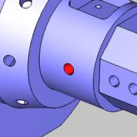
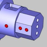
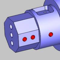
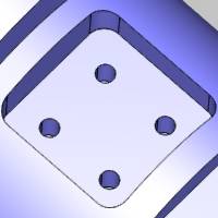
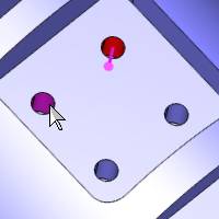
First, click to select the six holes at the base of the model, and then select the three holes on the front face of the model as shown next. (This order is necessary to obtain the results in the order they are described in this tutorial.)
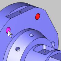
Note that for this example part and setup,
these are the only holes that can be drilled using standard drilling.
-
To confirm the selection, click OK.
Notice in the hole list of the Mill Hole Wizard, the 0.3750 diameter hole displays as having multiple depths. Click the 0.3750 hole in the list and notice that under Geometry Parameters, only the diameter can be changed. Click the 0.3125 hole in the list and notice the Geometry Parameters now displays the Diameter, Depth, and Pick Bottom.
Tip: In the Geometry Selection page, when you have more than one depth for a single diameter, the Depth (and Pick Bottom) becomes unavailable for that hole size, because it contains more than one hole group. The depths for each hole group can always be set in the Feature page of the wizard.
-
Click Next>>.
Define Feature Settings
Notice on the left side of the dialog box that two features are created from our selections: one for each hole diameter. For each feature (diameter), the holes that share the same top of feature and feature depth are automatically placed into a hole group. Because we selected cylindrical surfaces, the software automatically set all of these parameters in the wizard. (To learn about selecting other geometry types, view the Point and Arc Usage Example.) Next we confirm the proper settings for each hole group.
-
Under Hole Groups, click anywhere in the row of Group 1 to select it.
Notice the hole groups preview displays directly inside the dialog box. (You may or may not have the same group display, depending on which hole you selected first.)
-
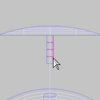
Click and drag in the preview window to rotate the model making it easier to view the feature preview (shown in pink).
Tip: To modify the viewing orientation of the hole groups preview, click and drag to rotate the view (left or middle mouse button). To pan the view, hold Ctrl and drag with the middle mouse button. Use the middle mouse button (roll forward or backward) to zoom in or out.
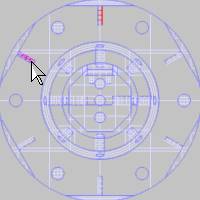
The hole groups preview shows that three
of the lower holes are a single group (same top of feature and feature
depth). The other three holes at the base have a different depth, so they
are placed in a separate group.
-
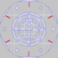
In the Hole Groups list, click anywhere in the row of Group 2 to select it and display the hole groups preview.
Again, we can see that the holes with the same top of feature, feature depth, and diameter are placed into a hole group. For now, we don't need to make any changes to the hole groups. -
Click Next>>.
Define the Machining Strategy and Tool Data
-
Under Template, click Hole.
Selecting this operation template adds one Center Drill and one Drill operation to the Current Operations list. -
On the lower-left side of the dialog box, click Apply to All Features.
This assigns the same operation template to the Machining Strategy of the second feature. -
Click Next>>.
For this example, we don't make any changes to the Posting or Multiaxis Posting settings, but notice the Posting Mode and Submachine groups. The Posting Mode determines how the machine performs the operations and how the code is output. With Auto/Y-axis mode, the spindle (C-axis) remains fixed and the milling spindle uses the Y-axis travel to move around the part (because we are using a machine that has Y-axis capabilities). The Submachine list is used to change the submachine from the default submachine that is selected under the Machine Setup in the CAM Tree. -
In the tree under the first Center Drill operation, click
 Center Drill.
For this example, we use the automatically selected System Tool information, but be sure to set all of the information in this page as needed for the job when creating your own program. -
Click Next>>.
No changes are made to the center drill parameters, but notice there are no hole groups listed. The center drill parameters apply to all hole groups in the feature. Center drill and chamfer operation parameters are applied to all hole groups in the feature, but all other drilling operations have hole-group specific parameters as shown later. -
Click Next>> twice to go to the Drill operation tool settings and notice again that System Tool is used to automatically assign our drill tool information from the Tool Library (after searching the Tool Crib).
-
Click Next>>.
Define Operation Parameters for Hole Groups
It is important to understand how to set the operation parameters for hole groups. As shown previously, operations such as center drill and chamfer use shared parameters for all hole groups, but all other operations contain a hole groups list so you can set the parameters separately for each group.
-
Notice the Use Cutting Conditions check box is selected. We use this option to allow the software to automatically calculate the effective depth and overall depth values for all hole groups.
It is important that you set the parameters for each hole group by selecting a group before making changes. -
Under Hole Groups, click to select Group 1 (it highlights in dark blue).
-
Under Cycle Type, click Peck.
-
Click to select Group 2 in the Hole Groups list.
Notice that pecking is not selected for this group because we have not changed it yet. -
Under Cycle Type, click Peck.
Both hole groups now use the same settings. -
Click Feature-0.3125.
Define the Second Feature
The second feature in the tree was created for the other hole diameter we selected. Next we define the settings for this feature.
-
Under Hole Groups, click to select Group 1.
The hole groups preview displays so we can confirm with which hole group we are working.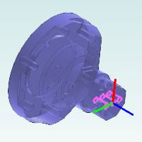
-
No changes are needed to the hole group parameters, because they were automatically set from selecting cylindrical surfaces.
Sometimes you need to modify the parameters for a hole group. The following steps explain how.
Editing Values in the Hole Groups Table
In the Hole Groups list, you can click anywhere in the row of a group to select the group, but if you click the name, top of feature, or feature depth value directly, it becomes available for editing (and the group is selected). When adding and removing selections in the Hole Groups list, you should click the far left side of the row (anywhere in the Number column).
-
Under Hole Groups, click the name Group 1.
Notice that the text is selected and available for editing. -
Type 0.3125 Top, and press Enter or click anywhere else to update the name.
Creating custom names for hole groups can be very helpful when there are many hole groups in a feature. The group names display in the parameters page for each operation, so descriptive names can make it easier to set the parameters for many hole groups. -
You can also click the Top of Feature value or the Feature Depth value directly to edit it in the table (no changes are needed for this example).
-
Click Next>>.
Finish the Feature and Compute the Toolpath
-
Notice the Machining Strategy is set to the Hole operation template, because we used Apply to All Features earlier.
-
In the tree on the left, under the last Drill operation, click Parameters.
Under Hole Groups, click to select 0.3125 Top. (Notice this is using our custom group name.) -
Under Cycle Type, click Peck.
-
Click Compute to calculate the toolpath.
Part 2) Understanding the Toolpath for Hole Groups
After computing the toolpath, we can see that it needs modified for one feature. It is important to understand how the material approach settings are applied to hole groups. The rapid plane is applied within hole groups and the rapid movement between hole groups is determined by the group retracts. Currently the tool movement within groups (rapid plane) is going through the model because we are currently using a Z-axis plane. This is easily resolved in the following steps.
The toolpath result is shown next.
The rapid movement through the part is shown next.
Notice that the rapid movement between hole groups retracts to a plane in front of the part, instead of using the rapid plane. This movement is defined by the group retracts. In the next part of this tutorial, we break the hole groups so that rapid movement between all holes uses the group retracts.
Part 3) Break Hole Group and Group Retracts
Next we edit the first feature to modify the hole groups and use our group retracts to customize the toolpath for our example part.
-
In the CAM Tree, click the first feature name Standard Feature Mill Hole - 0.3750.
Notice the feature highlight displays in the graphics area. This is an easy way to confirm the feature with which we are working.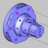
Click the name of the second feature, Standard Feature Mill Hole - 0.3125, to highlight it in the graphics area.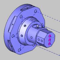
No changes are needed for our second feature. -
Right-click Standard Feature Mill Hole - 0.3750, and click Edit.
-
Under Hole Groups, (Group 2 may already be selected, but if not, click to select it first) hold Shift and click Group 1 so that both groups are selected.
Click Break Hole Group.
Notice there are now six groups. These groups each contain only a single hole, and the naming shows which group they came from (Group 1.1, Group 1.2, and Group 1.3 came from Group 1).
You can click each group in the list to display the hole groups preview and confirm the changes. -
Under Material Approach, click Group Retracts.
The group retracts determine the rapid movement used between hole groups, so all of our hole groups now use the group retracts instead of the rapid plane. -
Confirm that Plane is selected and change the Height value to 0.6250.
Click OK. -
Click Compute to update the toolpath.
After viewing the new toolpath, we edit the feature again, and change the group retracts Height value to -3.000. Note that this value is in reference to the machining origin coordinate system (which is at the front face of our part). The computed result is shown next.
To hide all toolpath created thus far, right-click Machine Setup, and click Blank/Unblank Toolpath.
This concludes the standard drilling portion of this tutorial. Next we create a feature using cross drilling to machine the drill holes in which the tool orientation (on the physical machine) is parallel to the X-axis and points to center line. Note that any X-axis drill holes that don't point to (or cross) the center line of the part require multiaxis (Y-axis) mill turn machines as shown later.
Part 4) Create a Mill Hole Feature (Cross Drilling)
Set Drilling Type and Select Geometry
-
Right-click Machine Setup, point to Mill Features, and click Mill Drill Hole.
-
Click Select Geometry.
-
Next to Standard Drill, click the down arrow, and select Cross Drill.
Notice the Rotation Axis parameter. This must be set to the rotational axis of the part on the machine, which is usually Z Axis, as it is for this example. -
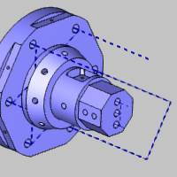
Next we select the cylindrical surfaces of all cross drill holes.
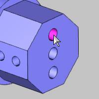
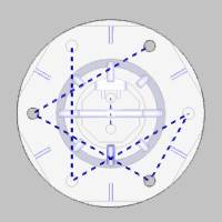
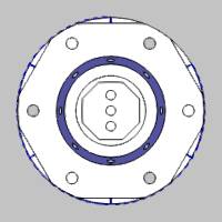
Select the six holes on the flats at the base of the model.
Tip: To make
the selection of the small cylindrical surfaces easier, use the following
steps.
• Click anywhere in the graphics
area, to give it key focus, and press Ctrl+5
to select the right view.
• Press the S
key to turn off the shaded view.
• Press the W
key to turn on the wireframe view.
You can now select the wireframe of the cylindrical
surfaces using a single view orientation, eliminating the need to zoom
in and out and rotate the part.
Press S and then press W to turn toggle these view options. Now press T to turn on the transparent view and confirm that the cylindrical surfaces are selected. (Press T again to turn off the transparent view.)
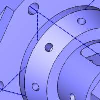
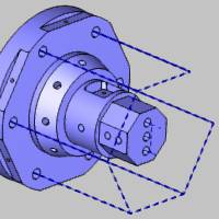
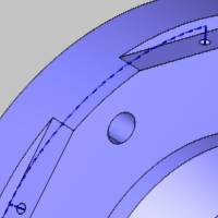
Rotate the model and select the through hole in the middle of the part.

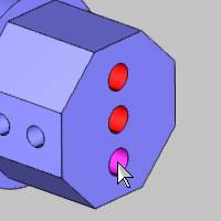
Select the four holes on the flats at the front of the part.
Note that the holes inside of the pocket cannot be drilled using cross drilling, because these holes do not point to center line, thus they require Y-axis (multiaxis) movement. This is also true for the angled holes, although they require more than Y-axis movement. These holes are machined later in the multiaxis portion of this tutorial.
Tip: The software automatically filters the geometry selections for each drilling type based on the hole orientation (and machining origin). Even if you selected the multiaxis holes shown in the previous images, they would be filtered out when you confirm the selections.
-
Click OK to finish geometry selection.
-
Click Next>>.
Define the Features and Compute Toolpath
-
Under Hole Groups, select Group 1 to display the hole groups preview.
For now, we do not change any feature settings. -
Click Next>>.
-
Under Template, click the Hole operation template, and click Apply to All Features.
-
In the tree on the left, click Feature-0.2500.
Select each group in the Hole Groups table to confirm the grouping of holes for this feature.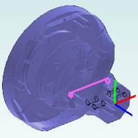
We can see that the through hole becomes its own group, and the other four holes become a single group because they share the same depth and top of feature.
No other changes are made for either of these features. For this example, we compute the toolpath first to check for any changes that need made. -
Click Compute.
Next we hide the toolpath of the second feature so we can focus on the first. -
Right-click the last feature name, Cross Feature Mill Hole - 0.2500, and click Blank/Unblank Toolpath.
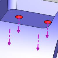
We can see that the toolpath for the first feature retracts above the flats, but has minimal clearance to the outer diameter of the part.
To add more clearance for these holes, we don't want to break the hole group, because we only need to increase the rapid plane value. (The cylindrical rapid movement shown here is the rapid plane and not the group retracts, because this is a single hole group.)
Edit the First Cross Drill Feature
-
Right-click Cross Feature Mill Hole - 0.1250, and click Edit.
-
Under Material Approach, change the Rapid Plane value to 0.3000.
-
Click Compute.
The toolpath now properly clears the outside of the part.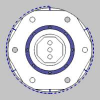
-
Right-click Cross Feature Mill Hole - 0.1250, and click Blank/Unblank Toolpath.
Edit the Second Cross Drill Feature
-
Right-click Cross Feature Mill Hole - 0.2500, and click Blank/Unblank Toolpath.
For the second cross drill feature, the toolpath is acceptable, but we want to make a few changes. For this toolpath, the rapid plane is properly clearing the flats on the front of the model when moving from one side to the other (within groups) so no change is needed. The retract distance between hole groups (group retracts) however, can be reduced. Also, we want to change the drilling order to the order in which we selected the holes. -
Right-click Cross Feature Mill Hole - 0.2500, and click Edit.
-
Click Group Retracts, and change the Radius value to 2.000.
Click OK. -
Under Machining Order, click Pick Order.
-
Click Compute.
Now the through-hole is drilled first before the holes at the front of the part, because we selected it first. The retracts between these two groups now use a two-inch radius. -
Right-click Cross Feature Mill Hole - 0.2500, and click Blank/Unblank Toolpath.
Next we create a multiaxis hole feature to drill the remaining holes in our example part.
Part 5) Create a Mill Hole Feature (Multiaxis Drilling)
Set Drilling Type and Select Geometry
-
Right-click Machine Setup, point to Mill Features, and click Mill Drill Hole.
-
Click Select Geometry.
-
Next to Standard Drill, click the down arrow, and select Multiaxis Drill.
-
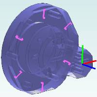
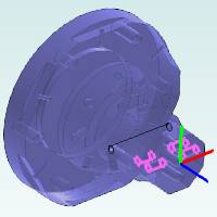
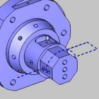
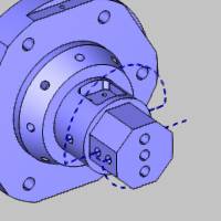
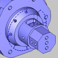
Click to select the cylindrical surfaces of all holes on the angled boss of the part.
You can click the surfaces and rotate the model to select all holes, or you can use the viewing options as explained earlier to select the holes without rotating the part.
We click anywhere in the workspace, to give it key focus, and press Ctrl+5 to select the right view. Then we press the S and W keys to turn off shaded view and turn on the wireframe view.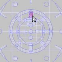
-
Select the cylindrical surface of the four holes in the pocket, as shown next. (We turn on the shaded view and turn off the wireframe view to select these holes. Press S and W, or in the document toolbar, click
 Shaded and
  Wireframe.)
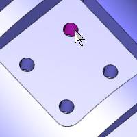
Now that all holes are selected, we need to confirm that the drilling direction is correct for all holes (the direction indicator points to the bottom of the hole).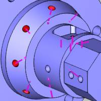
We can see that the drilling direction is correct for each hole. The software uses the model's center of mass to set the drilling direction, which for this part works perfectly. You may sometime need to reverse the direction when it is not towards the model's center of mass or when using other geometry types. To reverse the direction of one or more holes, select them in the Geometry list (selected items display in the highlight color on the part), and click Reverse. -
Click OK to close the Selection Manager.
-
In the hole list, click the 0.2500 hole size, and click to clear the Through Hole check box.
Repeat this step for the 0.1250 hole size.
Click Next>>.
Define the Feature Settings
-
Under Hole Groups, select Group 1 by clicking in the Number column.
The hole groups preview displays. -
Press the down arrow key to move through the groups and update the preview.
Notice each group contains a single hole. This is because each one of these holes has a different tool vector. Multiaxis hole groups must also share the same tool vector in addition to the diameter, top of feature, and feature depth. -
Click Group Retracts.
Next to Type, click the down arrow, and select Cylinder.
Change the Radius value to 2.000.
Click OK. -
On the lower left, click Apply Material Approach to All so that both features use the same group retracts, rapid plane, and feed plane.
-
Click Next>>.
-
Select the Hole operation template, and click Apply to All Features.
Note that we are again using many default settings to compute the toolpath. This is done only to reduce the length of the tutorial. You should always confirm or select all settings in the wizard when creating your own programs. You can get more information about all wizard parameters using this help system. -
Click Compute.
Note that the four holes at the bottom of the pocket require a mill-turn machine with Y-axis capabilities (4-axis). The angled holes in our other multiaxis feature require a multiaxis (5-axis) mill turn machine. We are currently using the BC 2T2S 5X machine which can handle all drilling creating in this tutorial.
This concludes the tutorial.