How to Create a 4 Axis Rotary Feature
Introduction
This tutorial provides an example of how to create a 4 Axis Rotary feature. This tutorial is supplemental to The 4 Axis Rotary Operation.
This tutorial explains the following functionality of the 4 Axis Rotary feature:
- How the toolpath is applied to the part
- Limiting the toolpath along the rotary axis
- Creating multiple depths (offset from the geometry)
- Using the Cut Interval option to determine the plunge location
- The importance of properly setting the Base Point and Direction parameters based on the rotary axis and machining origin
- Properly setting the Work Offset shift values for simulation
Example File
The BobCAD part file for this tutorial is available for download at: http://bobcad.com/helpfiles. If you are connected to the Internet, you can click the link provided to download and save the 4 Axis Rotary Example 1.bbcd zip file. After extracting the zip file, you can open the file to follow along with this example. In the example file provided, the stock and Machine Setup are already defined for the part. The program is simulated using the BC 4x Mill, which is a 4-axis machine with an A-axis rotary.
Part 1) Add the Feature
-
Open the example file: 4 Axis Rotary Example 1.bbcd
-
In the Data-CAM Tree Manager, click the CAM Tree Manager tab.
-
To add a feature, right-click
 Machine Setup,
and click Mill 4 Axis Rotary.
Machine Setup,
and click Mill 4 Axis Rotary.
The Mill 4 Axis Rotary Wizard displays.
Part 2) Select Geometry
-
Under Geometry Selection, click Select Geometry.
Click and drag a window to select the entire part.

-
To confirm the selection, click
 .
. -
Click Next>> to begin editing the Feature parameters.
Part 3) Define the Feature Parameters
-
In the Feature settings, notice that the Clearance Plane is automatically set using the value from the Machine Setup.
-
Change the Rapid Plane to 0.350.
-
Change the Feed Plane to 0.250.
-
The Top of Feature is automatically set (0.000) based on the selected geometry and machining origin.
-
Click Next>> to go to the Machining Strategy.
Part 4) Define the Machining Strategy
-
Confirm that there is one 4 Axis Rotary operation in the Current Operations list.
(You can add one or more 4 Axis Rotary operations to a single feature.) -
No other changes are needed.
Click Next>> to go to the Posting settings.
Part 5) Define the Posting Parameters
-
The Work Offset # is automatically set to the value previously defined in the Machine Setup.
You can update the Work Offset # for the feature here when needed. -
Click Next>> to go to the Multiaxis Posting settings.
Part 6) Define the Multiaxis Posting Parameters
-
Notice, at the top of the dialog box, that the Use Machine Settings check box is selected.
This means that the Multiaxis Posting parameters for the feature use the same parameters as the machine that is selected in Current Settings.
You can clear the Use Machine Settings check box to define the Multiaxis Posting parameters of the feature separately from the current machine settings.
For this example, no changes are needed. -
Click Next>> to go to the Tool settings.
Part 7) Define the Tool Parameters
-
In the Tool Data group, clear the
 System Tool check box.
Set the Diameter to 0.500 and the Flute Length to 3.000.
Set the Corner Radius to 0.250.
We are creating a new tool because the default Tool Library doesn't already contain a similar ball endmill. -
Click Assign Tool Holder.
-
Under CAT 40 Holder, click to select the 0.5 inch I.D. Arbor CAT 40, and click OK.
-
To finish the tool definition, click Next>>.
Part 8) The Pattern Dialog Box
-
In the Cut Pattern group, to define one-way cutting, Zig is selected.
-
Next to Style, click the down arrow and select Around.
Important: To create proper toolpaths with the Rotary feature, you must define the Direction and Base Point for the rotational axis of the part. The Base Point values are based on the machining origin location in reference to the center of rotation for the part. The following steps handle the machining origin at the top of the cylinder, as it is in this example. (If the machining origin is in-line with the rotary axis, then the Base Point values are set to zero. Placing the machining origin on the rotational axis of the part means there is no difference to report between the machining origin and the rotary axis.)
-
To set the direction of the rotary axis, under Rotary Axis, select X Axis.
Because the machining origin was moved away from the center of rotation, the difference must be defined using the Base Point parameter.
The following image shows the distance that is used to set the base point. This is the distance from (1) the machining origin to (2) the center of rotation of the part.
This parameter is an important part of proper toolpath creation.

(When the wizard is closed, you can click
![]() Machine Setup in the CAM Tree
to view the machining origin in the Workspace.)
Machine Setup in the CAM Tree
to view the machining origin in the Workspace.)
The only difference to report for this example is along the Z-axis. The radius of the part (and stock) is 3.2679 inches.
-
Under Base Point, in the Z box, type -3.2679.
-
Click Next>>.
Part 9) The Parameters Dialog Box
-
In the Finish group, we use the default Stepover value of 0.100.
-
To leave material for finishing, in the AllowanceXYZ box, type 0.050.
For this example, we can increase the tolerance value of our roughing operation to speed up calculation time.
Change the Machining Tolerance to 0.0050. -
To calculate the toolpath, click Compute.

Notice that a single toolpath pass is created that follows the selected surfaces along the entire length of the part.
The next step is to edit the feature and use the Along Rotary Axis options to limit the toolpath on the part.
Part 10) Edit the Feature and Limit the Toolpath
When you computed the toolpath, the 4 Axis Rotary feature was added to the CAM Tree. Next we limit the toolpath calculation so that it doesn't cut the entire part.
-
To edit the feature, in the CAM Tree, right-click
 Feature 4 Axis
Rotary, and click Edit.
Feature 4 Axis
Rotary, and click Edit. -
On the left side of the dialog box, click Parameters.
-
In the Along Rotary Axis group, select the
 End
check box, and type 4.00.
End
check box, and type 4.00.
This setting limits the toolpath to four inches from the machining origin.

You can also limit the toolpath by changing the Start parameter to define where the toolpath starts in relation to the Machine Setup, along the defined Rotary Axis Direction.
Tip: You can use the Along Rotary Axis parameters Start and End, to define where the toolpath starts and ends. (By default, the Rotary feature creates the toolpath by cutting in the positive direction along the selected rotary axis. For example, with a A-axis rotary (rotation around the X-axis) the toolpath is from left to right.)

Part 11) Create Multiple Passes
The next step is to add multiple passes to the feature.
-
In the Multiple Passes group, select the
Multiple
Passes check box. -
Under Roughing Passes, in the Number box, type 2.
In the Spacing box, type 0.250. -
Next to Sort By, click the arrow and select Passes.
This causes the feature to cut each pass before moving on to the next pass. In other words, this cuts the entire part to one depth before moving on to the next depth. -
To update the feature, click Compute.
The toolpath now contains two passes instead of the single pass created earlier.
Notice that the multiple passes are created from the selected surface and are layered outward. (They are not layered from the stock inward.)


Part 12) Change the Cut Interval
Before simulating the program, there is one last change to make. You can see in the toolpath from the previous step that the tool is plunging, at rapid rate, into one of the deepest areas of the part geometry. The next steps cause the tool to plunge into a more shallow area of the part.
-
Edit the feature, and click Patterns.
-
Under Angular Start/End, select the Cut Interval option.
-
In the Angle Start box, type -135.
-
In the Angle End box, type 225.
-
Click Compute.


Part 13) Simulate the Program
-
To simulate the toolpath, right-click Milling Job, and click Simulation.
To learn more about simulation, view Getting Started with Simulation.

Note: About the Toolpath Display - Rewinds:
When you simulate the program, you can see
a large circle in the toolpath. This circle in the toolpath represents
the tool retracting during the machine rewinds that result from the rotational
limits set for the machine (in the Machine Definition of the Default Current
Settings). Once the machine reaches its maximum rotational limit, the
rotary axis must rewind. The rewind can be seen in the middle of the program
simulation.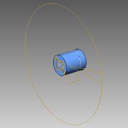
-
For this example, it is important to understand the Work Offset parameter that was previously defined in the Machine Setup dialog box.
To open the Machine Setup dialog box, in the CAM Tree, right-click Machine Setup,
and click Edit. -
In the Machine Setup dialog box, click Work Offset and notice the XYZ values.
These XYZ values represent the distance from the machine zero to the part zero (machining origin) defined in the Machine Setup. For this example, this is from the center of the face of the rotary table (virtual machine zero) to the machining origin that is on the top of the cylindrical stock. -
When the machining origin is not the same as the virtual machine zero, you must define the difference between these two coordinate systems using the Work Offset dialog box. This is necessary to create the proper machine simulation and posting.
To learn more about the 4 Axis Rotary feature, including Trim to Stock, view the 4 Axis Rotary Operation topic.
This concludes the tutorial.
Related Topics
The 4 Axis Rotary Operation