Assigning a Fixture
Introduction
Each of the machine setups in a milling job can have a unique fixture assigned to it. This example explains how to assign components as a fixture in a machine setup. In this example, once we assign the fixture, we will also view the fixture in simulation.
This example will have you:
- Assigning the Fixture
- Simulate the Milling Job
Example Part
The part file for this example is available for download http://bobcad.com/helpfiles.
If you are connected to the Internet, you can click the link provided
to download and save the SlottedPart_and_FixtureSub1.zip
file. After extracting the zip file, you can open the SlottedPart_and_FixtureSub1
| Machine Setup 1 |
|
Part 1) Assigning the Fixture
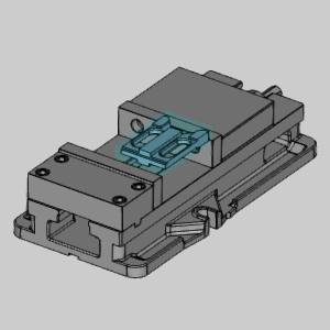
With everything in the job completed already, we could simply simulate, and post out the code. However, in order to see the fixture in the simulation, and check it for collisions, we will need to assign geometry as our fixture.
- Click on the CAM Tree Manager tab.
- Click the
 icon next to
  Machine Setup - 1 in order to expand it.
 - Right-click
 Fixture, and select Re/Select.
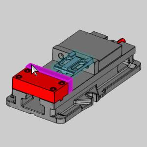
The Fixture dialog appears with focus on the Solid Body list. - Select each component of the vise.
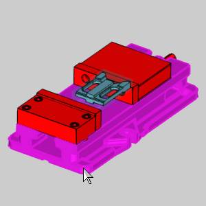
Note: Since the fixture selection is used to check for collisions in the simulation, you may choose to leave particular aspects of the vise assembly unselected.
- Click
 (OK).
(OK).
The Fixture dialog closes, and the icon is no longer seen in front of the Fixture item in the CAM Tree. This shows that geometry is currently assigned.
Part 2) Simulate the Milling Job
With the fixture assigned, we can now view it in the simulation.
- Right-click the
 Milling Job, and select Simulation.
The simulation launches. - Click
 Run.
Run.
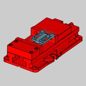
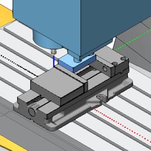
Notice the fixture is visible in the simulation. With the fixture assigned, collisions with it and other components in the simulation will be reported.
| Machine Setup - 1 |
|
- Click
 (Exit) at the top right of the simulation window to close the simulation.
This concludes this example.