


 Point Perpendicular
Introduction
This topic will explain the Point Perpendicular function, and the optionsfound in it.This topic will also describe where to find the function,provide quick steps and an example on how to use it, and provide links to related topics.
The Point Perpendicular Function
The Point Perpendicular function is used to create points on existinggeometry, at a location that is perpendicular from another selected pointgeometry.This is accomplished by selecting a point, and wireframe geometry,or visa versa.
Note: As seen below, this function willalso produce points on what would be the extension of the selected wireframeentity.
Navigation
To open Point Sketch / Enter:
-
In the Entity groupof the Create 2D ribbon, click the down arrow under
 Point, and select
  Point Perpendicular.
The parameters display in the Data Entry Manager.
Note: Whether you click the main icon, or the down arrow to get to the other options, you will have access to the same options in the Data Entry Manager.
The Data Entry Parameters
Selected Geometries
The Selected Geometries list, shows the entitychosen for the creation of a perpendicular point.
Selected Geometry
|
|
|
| This list box will show the entities currently selected for the function. | |
 (Delete All)- removes all entities from the list.
-
OK - has no use with this function.
- Cancel - Closesthe function without creating previewed points.
Point Perpendicular - Quick Steps
- To perform the function, move yourmouse into the graphics area, and select either:
- The point
- The wireframe entity
- Select the other entity.
The perpendicular point is created. - Continue this process to create the neededpoints.
- To close the function, click Cancel.
Example
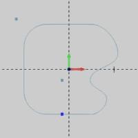
Part 1) Create Example Geometry
- in the Quick Access Toolbar, click
 New.
New. - In the Shapes group, of the Create 2D ribbon,click
 Rectangle.
The Rectangle parameters display in the Data Entry Manager. - Under Corner Type,click Radius.
In the Radius box, change thevalue to 0.500, and pressTab to update that CAD preview.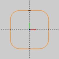
To create the rectangle as shown in the CAD preview, click OK.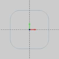
To end the function, click Cancel. - In the Document Toolbar, click
 Select Mode.
In the graphics area, click to select the upper arc, the vertical line,and the lower arc on the right side of the rectangle.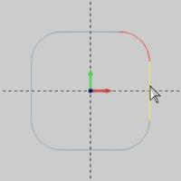
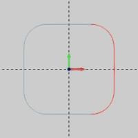
Press the Delete key.(Alternatively,in the Edit group, of the Home ribbon, click Delete.)
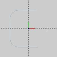
- In the Entity groupof the Create 2D ribbon, click the down arrow under
 Spline, and select
  Blended.
In the graphics area, click near the right side of the upper line todefine the start of the spline.(If the line is not highlighted whenyou click it, the spline will not be connected to the line.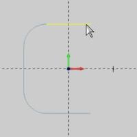
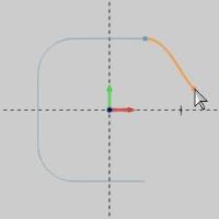
Sketch the spline by clicking three times as you move towards the lowerline.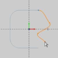
To define the end of the spine, click near the right side of the lowerline.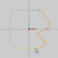
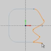
To confirm the selections and finish the spline, press the Spacebar.(Alternatively, right-click in the graphics area, and click OK.)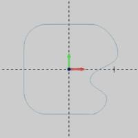
- In the Entity groupof the Create 2D ribbon, click
 Point.
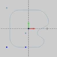
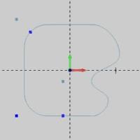
Click twice to create two points similar to the image shown next.Besure to create one of the points to the left of the vertical lineand above the upper horizontal line.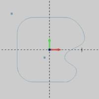
- To end the function, click Cancel.
Part 2) Create Points Using Point Perpendicular
- In the Entity groupof the Create 2D ribbon, click the down arrow underPoint, and select Point Perpendicular.
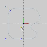
- Move the pointer to the reference point thatis inside the geometry (so that it displays in the Highlight color),and click to select it.
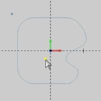
The reference point changes to the selection color.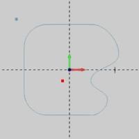
Note: When usingPoint Perpendicular, you can select the reference point or the wireframeentity first.The result of the function is the same for either method.In this example, we select the reference point first so that we can usethe CAD preview to see where the (perpendicular) point will be createdon any of the wireframe entities before performing the function.
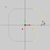
Point to the spline, and notice the CAD preview.
Point to the lower line and click to createthe point.(In the following images, the active drawing color was changedto make it easier to see the points created with Point Perpendicular.)
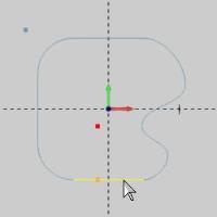
That is all that is needed to perform thefunction.You can repeat this process to create many points as needed.
How it Works
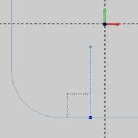
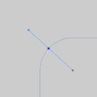
The following image shows that Point Perpendicular creates a point ata right angle to the wireframe entity from the reference point.If youcreate a line between the reference point and the perpendicular point,it forms a right angle with the wireframe entity.
Part 3) Create Perpendicular Points as an Extension of the WireframeEntity
- Click the reference point (inside the contour)again to select it and enable the CAD preview.
- Point to both the lower and upper arcs, andnotice where the CAD preview displays for each.
You can see that the preview does not appear on the arc entities.Inthis case the preview shows that the point will be created as an extensionof the arc geometry.Before getting into detail about how the functionworks with arcs, we create a perpendicular point as an extension ofa line. - Click the reference point again to removeit from the selection.(After selecting the first entity, you canclick it a second time to clear the selection and start over.)
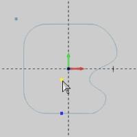
Select the reference point in Quadrant 2.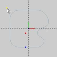
- Point to each of the three lines, and noticewhere the CAD preview displays the point.
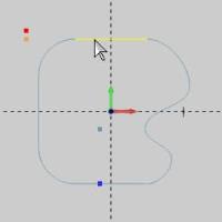
You can see that the perpendicular point will be created as an extensionof the lines.It does not have to be on the wireframe (lines). - Click the lower horizontal line to createa point.
You can see that the point is created as an extension of the line inorder to make a right angle between the reference point and the line.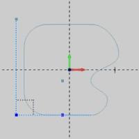
Part 4) Using Point Perpendicular with Arcs
When using Point Perpendicular, the software draws a line between thereference point and the arc center.It then creates the point at the intersectionof this line and the arc.As a result, the point may be on the arc, orit is created as an extension of the arc.(The point is always placedalong the radius of the arc.)
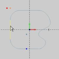
- Click the reference point that is outsidethe contour.
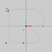
- Click the upper arc.
- If you were to draw a line between the referencepoint and the arc center, you can see that the point is created atthe intersection of the line and the arc.
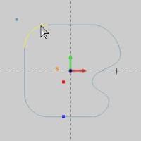
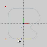
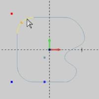
- Click the reference point that is insidethe contour.
- Click the upper arc.


Notice the point is not created on the arc,but rather as an extension of the arc (as if it was a circle).As explainedearlier, a line is drawn from the arc center to the reference point, andthe point is created along the radius of the arc.This is shown in thefollowing image.

- To end the function, click Cancel.
This concludes the example.