


 Section View
Introduction
This topic will explain the Section View function, and the optionsfound in it.This topic will also describe where to find the function,provide quick steps on how to use it, and provide links to related topics.
The Section View Function
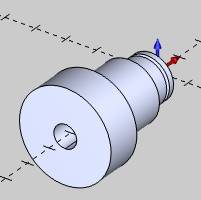
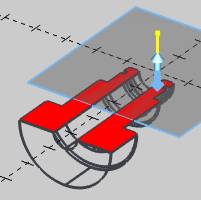
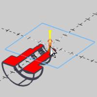
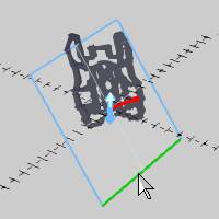
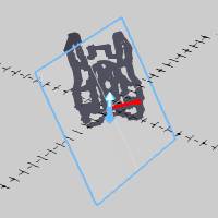
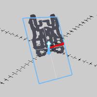
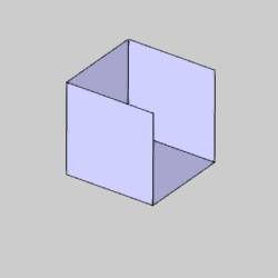
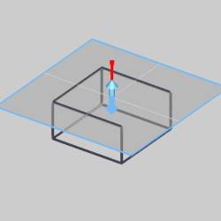
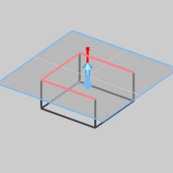
The Section View function is used to create a sectional view of solidgeometry in the graphics area.This also includes the ability to create wireframegeometry by extracting the edges currently visible in the section view.When opening Section View, the solid model displays using wireframe andthe Section View viewing plane displays.You can click the arrows in thecenter, or the edges of the viewing plane, to manually update the viewingplane position and orientation.Also, next to the arrows in the centerof the viewing plane is the normal indicator, which represents the positivedirection used for modifying the viewing plane parameters.
Navigation
To open Section View:
-
In the Utilities group, of the Create 2D ribbon, click
 Section View.
The parameters display in the Data Entry Manager.
The Data Entry Parameters
Selected Solids
|
|
|
| This list box will show the entities currently selected for the function. | |
 (Delete All)- removes all entities from the list.
- Confirm Selection - when geometry is added to the Selected Solids list, click Confirm Selection to update the section view.Using particular solids will not update the location of the section view, but will update what solids are shown with a section view.
Section Plane
You can select the viewing plane using one of the two following methods.
-
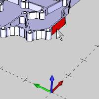
 Pick a Surface - enablesselection mode for you to click a solid face or surface to set theviewing plane zero location and orientation.
|
|
|
| The list box will list the entity currently selected for the function. | |
-
 UCS - allows you to selectany user coordinate system from the UCS Manager to set the viewingplane zero location and orientation.Click the down arrow to selecta UCS from the list.
|
|
Top (X/Y) | - uses the Top plane as the section view. |
| Front (X/Z) | - uses the Front plane as the section view | |
| Side (Y/Z) | - uses the Side plane as the section view | |
| Custom | - lists any custom UCS planes the user may have created to use as the section view |
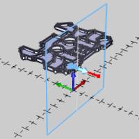
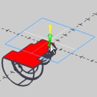
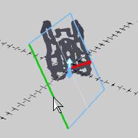
- Distance - sets the Z-axisposition of the viewing plane in reference to the selected face orUCS zero.Type a positive or negative value to update the viewingplane.You can also update the distance by clicking the arrows thatdisplay on the viewing plane in the Workspace and then clicking anew location.
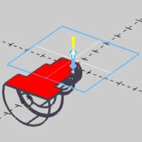
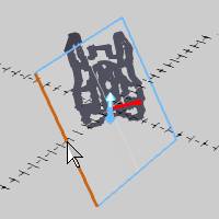
- Rotation X - sets the amountof X-axis rotation for the viewing plane.When using Pick a Surface,the selected surface becomes the zero for the rotation angle.Youcan also update this distance by clicking either side of the viewingplane (parallel to the X-axis) in the Workspace and rotating the plane.
- Rotation Y - sets the amountof Y-axis rotation for the viewing plane.When using Pick a Surface,the selected surface becomes the zero for the rotation angle.Youcan also update this distance by clicking either side of the viewingplane (parallel to the Y-axis) in the Workspace and rotating the plane.
Tip: Afterusing the section view handles to change the Distance or Rotation parameters,you can then update the values in the Data Entry Manager if needed.
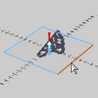
Generate Wireframe
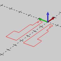
- Create Wireframe - extractsthe visible edges of a solid from the current sectional viewing planeand places the wireframe entities on the Active Layer.
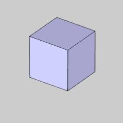
- Allow Open Chains
 - With this option cleared, surfaces that do not form a closed chain will not be utilize when creating a wireframe.
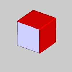
 - With this option selected, wireframe will be created from any surface regardless of whether it creates a closed chain.
| Example Surfaces | ||||||
|
|
|
||||
|
||||||
- Reset - returnsthe Distance, Rotation X, and Rotation Y values to zero.
- Cancel - closes theData Entry Manager.
Quick Steps - Section View
-
Open the function and select the viewingplane using either Pick a Surface or by selecting a UCS from the list.
-
Update the Distance and Rotation values usingeither Data Entry or by clicking the drag handles on the section viewplane in the Workspace.
-
If you want to extract the visible edgesand create wireframe geometry, click GenerateWireframe.
-
To reset the section view parameters to theselected UCS or surface, click Reset.
This is helpful if you want to create a sectional view for anothersolid. -
To close the function, click Cancel.