


 Silhouette
Introduction
This topic will explain where to find the Silhouette function, andexplain the options found in it.This topic will also give quick steps, an example, and provide links to related topics.
The Silhouette Function
The Silhouette function creates wireframe curves pulled from the outline of the selected geometry.The user is also able to control the placement of the curves by adjusting the percentage values in the parameters or free hand by using mouse location.
Navigation
To open Extract Isocurve:
-
In the Utilities group, of the Create 2D ribbon, click
Silhouette.
The parameters display in the Data Entry Manager.
The Data Entry Parameters
Selected Geometry
|
|
|
| The list will display all entities currently selected for the function. | |
 (Delete All)
- removes all entities from the Selected Geometry list.
(Delete All)
- removes all entities from the Selected Geometry list.
 Direction
Method
-
Pick - allows you to select a line to set as the vector of the projection direction.
-
Existing UCS - allows you to select an existing UCS.When selected, the curve will be projected along the Z axis.
-
Enter - allows you to enter a particular axis of the current UCS to use, or enter a vector manually.
Options
-
Mesh Tolerance - determines the tolerance for the creation of the mesh model the silhouette is then extracted from.In the case of selecting STL models this tolerance is not used.
-
Arc Fit - in some cases what appears to be an arc is actually many individual line segments.This option allows you to create arcs from those segments when possible.
 - Converts strings of individual segments into arcs when possible based on the tolerance set.
 - Does not attempt to convert strings of individual segments into arcs.
 -
Merge All
- Creates an overall outline even when multiple pieces of geometry are selected. - Creates an outline for each piece of selected geometry. -
Internal Shapes
- Creates both an external and internal outline of the selected geometry. - Creates only an external outline of the geometry and ignores and internal outlines.
| Example Part | |||

|
|||
|
|
|
|
|

|

|

|

|
- OK - finalizes the function.
- Cancel - exits the function.
Quick Steps - Silhouette
- When the function is open the Selected Geometry list automatically has focus.
Select the geometry to pull outlines from.
The geometry is added to the Select Geometry list. - Update the directions to dictate which orientation the silhouette is pulled from.
- In the Options group, set the Mesh Tolerance when selecting NURB geometry, then set the Arc Fit, Merge All, and Internal Shapes options as necessary.
- Click OK to confirm the result.
- Repeat this process as needed for any other silhouettes to be extracted.
- To close the function, click Cancel.
Example - Extract Isocurve
- In the Quick Access Toolbar, click
 New.
New. - In the Primitives group, of the Create 3D tab, click
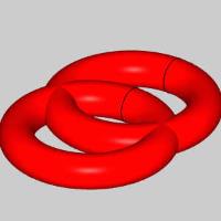
 Torus.
The preview appears.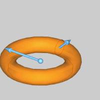
- Leave the default values as they are and click OK.
The torus is created.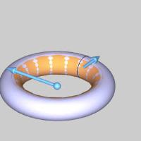
- In the Origin group, update the X value to 1.000.
The preview updates.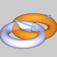
- Click OK.

-
In the Utilitiesgroup, of the Create 2D ribbon, click
Silhouette. -
In the Layers Manager, click
 to add a layer.
The new layer is automatically set as the active layer. -
Select both solids.
-
In the Options group, deselect Internal Shapes and click OK.
The silhouette is created. -
Hide the CAD layer to view the silhouette.
Notice there are two separate outlines for each solid. -
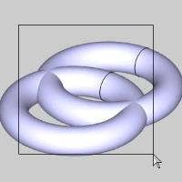
Press Ctrl+Z to undo and show the CAD layer again.
-
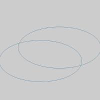
Select the check box for Internal Shapes and create another silhouette.

Notice we now have the internal and external outlines for each. -
Clear the check box for Internal Shapes, select Merge All and repeat this process.
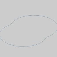
Notice we now have an overall outline of both solids handled as a single item. -
Select the check box for Internal Shapes and repeat this process.

In this case we still handle all solids as a single item but we now show the internal outline as well.
That concludes this example.