


 Unwrap
Introduction
This topic will explain the Unwrap function, and the optionsfound in it.This topic will also describe where to find the function,provide quick steps and an example on how to use it, and provide links to related topics.
The Unwrap Function
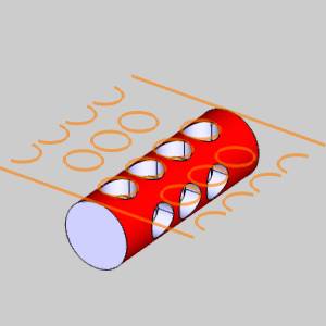
The Unwrap function unwraps cylindrical geometry to create groups of2D geometric entities.
Navigation
To open Unwrap:
-
In the Utilities group,of the Create 2D ribbon, click
 Unwrap.
The parameters display in the Data Entry Manager.
The Data Entry Parameters
Selected Geometry
|
|
|
| The list will display all entities currently selected for the function. | |
 (Delete All)
- removes all entities from the Selected Geometry list.
(Delete All)
- removes all entities from the Selected Geometry list.Diameter
-
 Automatic - uses theselected cylindrical geometry to define the unwrap diameter.
 -
 User Defined - selectthis option to type the unwrap diameter in the available textbox.
-
 Chaining Selected Geometry - alters the position of the unwrapped geometry to leave geometry that can be a closed chain, as a closed chain.
 Chaining Selected Geometry - leaves the geometry as it is and unwraps regardless of where the seam lays.
|
|
|

|
|
Center Axis
-
Pick Axis - requires a line to be selected asthe axis around which the geometry is unwrapped. Pick Axis - enables the Origin and Direction parameters for you to type values to define the axis to use for the unwrap.
Tip: When theselected geometry to unwrap is parallel to an X, Y, or Z axis, using Pick Axis is notnecessary.When it is askew of an axis, Pick Axis makes it simple.See the images below for a situational example of each.
The following parameters vary depending on the Pick Axis option that is chosen:
![]() Pick Axis
Pick Axis
- Along X Axis - sets the X axis as the axis to unwrap from.
- Along Y Axis - sets the Y axis as the axis to unwrap from.
- Along Z Axis - sets the Z axis as the axis to unwrap from.
- Customized Axis - allows for a custom axis to be used as the axis to unwrap from.
![]() Pick Axis
Pick Axis
Selected Center Axis
|
|
|
| The list box will list the entity currently selected for the function. | |
Note: The direction definesthe vector of the rotation.The direction values are always visible, but can only be edited when Pick Axis is not selected, and the Customized Axis option is chosen.When it is, type in the desired values in the X,Y, Z boxes to define the direction from the Origin Point.
- Origin X - sets the X value for the center of unwrap function.
- Origin Y - sets the Y value for the center of unwrap function.
- Origin Z - sets the Z value for the center of unwrap function.
- Direction X - lists the x value for the vector of the unwrap axis.
- Direction Y - lists the y value for the vector of the unwrap axis.
- Direction Z - lists the z value for the vector of the unwrap axis.
- OK - finalizes the function.
- Cancel - exits the function.
Quick Steps - Unwrap
- Open the function.
The Selected Geometry list automatically has function. - Select the geometry to unwrap.
The geometry is added to the Selected Geometry list.
A preview is automatically displayed, showing the results with the default options. - Set the Diameter to be unwrapped.
- Choose whether or not to use the Chaining Selected Geometry option.
- Define the Center Axis.
- Confirm the result.
The geometry is unwrapped. - Click Cancel to close the function.
Example
Part 1) Part Orientation and the Unwrap Rotation Center Axis Overview
-
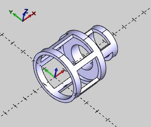
The Unwrap function can accommodate variouspart orientations.When the rotational center of the part is aligneddirectly along the X-, Y-, or Z-axis, set the UnwrapRotation Center Axis to the appropriate axis.
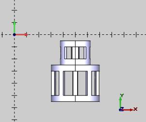
For the following example, X Axis is selected.
|
Example Part with X-Axis Orientation |
|
-
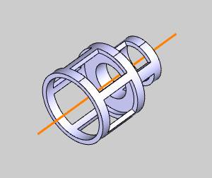
You can also draw a line through the rotational center of thecylinder to manually select as the Unwrap Rotation Center Axis.Youselect the line after selecting the unwrap geometry.
|
Using a Line for the Unwrap CenterAxis |
|
-
Another way to deal with custom part orientations is to usethe User Defined option.
When selected, the Originand Direction groups become available.
In the Origingroup, type X-, Y-,and Z- values to define a pointalong the Unwrap Rotation Center Axis.
In the Directiongroup, type the X-, Y-,and Z- values to define the directionfrom the Origin.
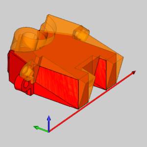
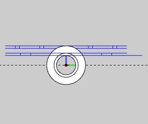
For example, the following image shows the partwith the center axis aligned to +X5 (parallel to the Y-axis).
Notice that the Direction values define the directionas parallel to the Y-axis.
|
User Defined for the Unwrap CenterAxis |
|
|
UserDefined Values |
|||
| Origin | Direction | ||
|
X |
5.000 |
X |
0.000 |
|
Y |
0.000 |
Y |
1.000 |
|
Z |
0.000 |
Z |
0.000 |
Notice that the Origin values define a pointalong the rotational center of the part in the graphics area.
Notice that Direction, X0Y1Z0, is a vectorthat defines the direction of the rotational center of the part as parallelto the Y-axis.
Part 2) Using the Automatic option for the Unwrap Diameter
For this example, the part is oriented along the X-axis as shown inPart 1.
-
In the UnwrapRotation Center Axis group, select XAxis.
-
In the graphicsarea, drag a window to select the entire part.
Press the Spacebarto confirm the selection.
|
Geometry Selection |
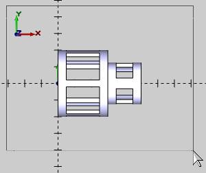
|
-
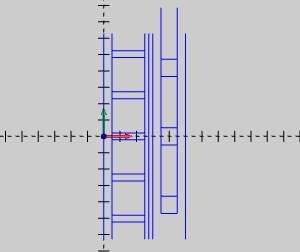
The geometry is unwrapped using the actual diameter of eachsection of the part.
In the next image, the part is hidden to bettershow the unwrapped geometry.
|
Unwrapped Geometry Top View |
Right View with Part Shown |

|

|
-
To exit the Unwrap function,in the Data Entry tab, clickCancel.
Part 3) Using the User Defined option for the Unwrap Diameter
This example uses the same part and orientation as in Part 2.For thisexample, the geometry is unwrapped using the greatest diameter of thepart which is 4 units.
-
In the Utilities group,of the Create 2D ribbon, click
Unwrap. - In theUnwrap Diameter group, selectUser Defined.
-
In the UserDefined box, type 4.00.
-
In the UnwrapRotation Center Axis group, select XAxis.
-
In the graphicsarea, drag a window to select the entire part.
To confirm the selection, press Spacebar.
|
Geometry Selection |
|
|
-
The geometry is unwrapped using the User Defined value of 4.00units.
In the next image, the part is hidden to bettershow the unwrapped geometry.
|
Unwrapped Geometry Top View |
RightView with Part Shown |
|
|
-
To exit the Unwrap function,in the Data Entry tab, clickCancel.
This concludes the example.