


 Offset Surface
Introduction
This topic will explain the Offset Surface function, will explain whereto find the function, and explain the options found in it.This topicwill also explain creation with quick steps and an example, and provide links to relatedtopics.
The Offset Surface Function
The Offset function creates an additional surface from an existing surfaceusing the offset value as the distance between the two.You can also usethis function to offset solid geometry.

Navigation
To open the Offset Surfaces function:
- In the Advanced Surfaces group, of the Create 3D tab, click
 Offset Surfaces.
The parameters display in theData Entry Manager.
The Data Entry Parameters
Selected Geometry
|
|
|
| The list will display all entities currently selected for the function. | |
 (Delete All)
- removes all entities from the Selected Geometry list.
(Delete All)
- removes all entities from the Selected Geometry list.- ShowPreview - Once geometry has been added to the Picked Entitieslist, clicking the Show Preview, displays the result that will becreated when you click OK.
Hide Preview- When the preview is displayed, the Hide Preview option will replaceit.Selecting the Hide Preview option will blank the preview.
Parameters
Distance- sets how far the selected geometry is offset.Negative values are supportedto offset in the opposite direction.
Tip: The positivedirection is the same as the surface normal direction of the selectedsurface.
 Options
The Options group includes check boxes to allow you to control the creationof fillets and to keep or remove the original surface upon the creationof the offset.This group can be expanded and collapsed with the , and  icons.
 Fillet Edges- When selected, this option adds a fillet to the offset geometrywhen corners exist.
![]() Fillet Edges - Whencleared, sharp edges on the existing surface, will be retained.
Fillet Edges - Whencleared, sharp edges on the existing surface, will be retained.
-
Keep Original - When selected, this option retainsthe original surface when the offset surface is created.
![]() Keep Original -When cleared, this option will replace the original surface with the newoffset surface.
Keep Original -When cleared, this option will replace the original surface with the newoffset surface.
- OK - finalizes the function.
- Cancel - exits the function.
Quick Steps - Offset Surfaces
- Open the function.
The Selected Geometry list is automatically given focus. - Select the surfaces to offset.
The surfaces are added to the Selected Geometry list. - Select the Show Preview button to see a preview of the offset.
- Set the desired parameters.
The preview updates. - Click OK to create the offset.
The feature is added to the CAD Tree. - Repeat as necessary.
Tip: Instead of applying features to solids and surfaces more than once, go to the CAD Tree to edit the existing feature. Since all solid and surface moves, and modifications are stored in the CAD Tree, editing a feature is preferable to adding many more to achieve the desired result. This will keep file size down and help ensure files don't become slow to respond.
- Click Cancel to exit the function.
Example
In this example, you will create geometryand then learn how to use the Offset Surface function on that geometry.This example will have you:
-
Create a Cube
-
Unstitch the Cube
- Move to the Front Plane
- Create a Rectangular Plane
- Create an Arc
- Move to the Top Plane
- Extrude the Arc
- Offset Without Keeping the Original
- Offset and Keep Original
- Offset with Filleted Edges
Note: Inthe images below, both the Show AxisX-Y and Show Gnomon toggleshave been disabled in the Axis X-Ygroup of the Settings Part > Displaydialog.
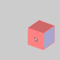
Part 1) Create a Cube
-
In the Quick Access Toolbar, click
 New.
New.
A new document opens. -
Enter into an ISO2 view by pressing Ctrl+7.
-
In the Primitives group, of the Create 3D tab, click
 Cube.
Cube.
The Cube parameters display in the Data EntryManager.
The Preview appears.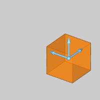
-
The cube being createdwill be left at the default size, and location.
Click OK to confirm the cube.
The Cube is created in the graphics area and a Cube feature is created inthe  CADTree.
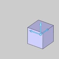
Part 2) Unstitch the Cube
-
In the Modify group,of the Create 3D ribbon, click the down arrow for
 Stitch Surfaces to Solid, and select
  Unstitch Surface from Solid.
 -
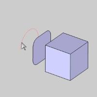
Hover over thesurface as seen in the image below.
The surface highlights.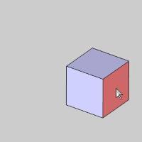
-
Click the surface.
The surface is added to the Selected Geometry list.
- Click OK.
The surface is no longer highlighted until the mouse is moved again.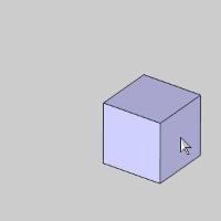
No change is visible, but the surface is unstitched from the cube andanUnstitchSurface from Solid feature is created in the CAD Tree. -
Click Cancel to exit the function.
-
Hover of a differentsurface of the cube as seen in the image below.
Notice the surface has been unstitched from the cube.
Part 3) Move to the Front Plane
-
In the UCSManager, clickFront(X/Z) in order to create another surface on the Front Plane.
The Front Plane highlights.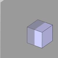
Part 4) Create a Rectangular Plane
-
In the Surfaces group, of the Create 3D ribbon,click the down arrow under
 Planar, and select
  Rectangular Plane.
The Rectangular Plane dialog opens in the Data Entry Manager. -
In the Base Point group, change the Z valueto -2.0000.
The preview updates.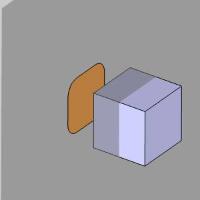
-
Click OK to confirm placement of the RectangularPlane.
The surface is created in the graphics area and aRectangular Plane feature is addedto the CADTree.
Part 5) Create an Arc
-
In the Entity group, of the Create 2D ribbon, click the down arrow under
 Arc, and select
  Arc Center.
The Arc Center dialog opens in the Data Entry Manager and the Preview displays.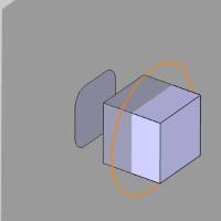
-
Update the valuesin the Arc Coordinate dialog to match the following:
|
Center X Center Y Center Z Radius Start Angle End Angle |
= 0.0000 = 0.0000 = -3.0000 = 1.0000 = 0.0000 = 180.0000 |
ThePreview updates.
-
Click OKto confirm the placement of the arc.
Part 6) Move to the Top Plane
-
In the UCSManager, clickTop(X/Y) to set it as the active UCS.
The Front Plane disappears.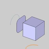
Part 7) Extrude the Arc
-
In the Extrude group, of the Create 3D ribbon,click
 Extrude Curve.
The Extrude Curve dialog opens in the Data Entry Manager. -
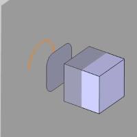
Hover over thearc as seen in the image below.
-
Click the arc.
The Preview appears.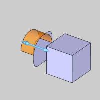
-
In the Positive Direction group, changethe Distance value to 0.0000.
The Distance in the Other Direction group automatically becomes 1.0000,and the preview updates.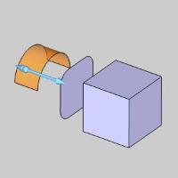
-
Click OK to create the Extrude Curve.
The Extrude Curve is created in the graphics area and an ExtrudeCurve feature is added to the CADTree.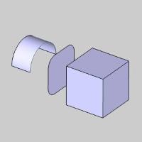
Part 8) Offset Without Keeping the Original
-
In the Advanced Surfaces group, of the Create 3D tab, click
Offset Surfaces.
The Offset Surface dialog opens in the Data Entry Manager. -
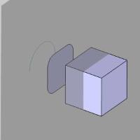
Hover over theextruded arc as seen in the image below.
-
Click the surface.
The surface is selected and is added to the Selected Geometry list.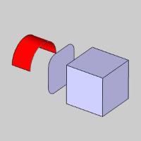
-
In the Parameters group, change the Distance to 0.5000.
-
Next to Options, click
to access the options if nothing is visible. -
Clear the checkbox for Keep Original.
The offset we create will now replace the original surface. -
Click Show Preview.
The Preview appears.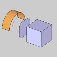
-
Click OK to confirm the surface.
The offset is created in the graphics area and anOffset Surface feature iscreated in the CAD Tree.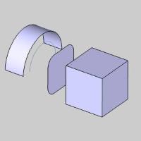
Part 9) Offset and Keep Original
-
Hover over therectangular plane as seen in the image below.
-
Click the rectangularplane.
The rectangular plane is added to the Selected Geometry list.
With the Show Preview button still selected, the Preview automaticallyappears.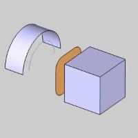
-
In the Parameters group, change the Distance value to -0.5000.
The Preview updates.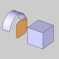
-
In the Options group, select the checkbox for Keep Original.
The offset we create will now be in addition to the original surface. -
Click OK to confirm.
The offset is created in the graphics area and an Offset Surface feature iscreated in the CAD Tree.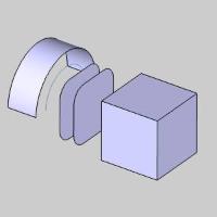
Part 10) Offset with Filleted Edges
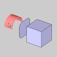
- In the Optionsgroup, clear the check box for FilletEdges.
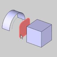
- Hover over the cube as seen in the image below.
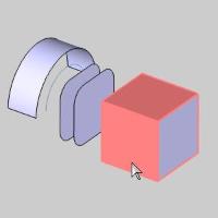
- Click the cube.
The cube is selected and added to the Selected Geometry list.
The Preview appears.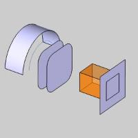
- In the Parametersgroup, change the Distancevalue to 0.5000.
The Preview updates.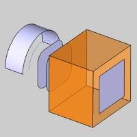
- In the Optionsgroup, select the check box for FilletEdges.
The Preview updates.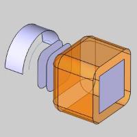
- Click OK to confirm.
The offset is created in the graphics area and another OffsetSurface feature is created in the CAD Tree.
- To end this function, click Cancel.
This concludes the example.