


 Ruled Surface
Introduction
This topic will explain the Ruled Surface function, will explain whereto find the function, and explain the options found in it.This topicwill also explain creation with quick steps and an example, and provide links to relatedtopics.
The Ruled Surface Function
The Ruled Surface function creates surfaces using the selection of twowireframe chains with a linear blending between the entities of each chain.The two chains need to share the same general chain direction to createthe proper results.The two chains can be connected to form the boundaryof the surface, or the software automatically creates the boundary oftwo non-connected chains.Generally, the chains should be the same numberof entities.
Navigation
To open the Ruled Surface function:
- In the Advanced Surfaces group, of the Create 3D tab, click
 Ruled Surface.
The parameters display in theData Entry Manager.
The Data Entry Parameters
-
 Preview - Select the check box to enable the CAD preview, which displays what the result will be before you create it. Once all geometry is selected, the preview is shown.
  Preview - Clear the check box
to turn off the CAD preview.
Preview - Clear the check box
to turn off the CAD preview.
Selected Geometry
|
|
|
| This list box will show the entities currently selected for the function. | |
 (Delete All)- removes all entities from the list.
- OK - finalizes the function.
- Cancel - exits the function.
Quick Steps - Ruled Surface
- Open the function.
The Selected Geometry list automatically has focus. - Chain select the first chain.
The chain is added to the Selected Geometry list. - Chain select the next chain.
The chain is added to the Selected Geometry list.
The Preview appears. - Click OK to confirm creation.
The feature is added to the CAD Tree. - Repeat as necessary.
- Click Cancel to exit the function.
Example
A BobCAD file installed with the software can be opened to follow alongwith this example.
Part 1) Open the Example File
-
In the Quick Access Toolbar, click
 Open.
Open. -
In the Opendialog box, navigate to C:\BobCAD-CAMData\BobCAD-CAM V**\Examples.
- With RuledSurface Example.bbcd displaying in the FileName box, click Open.
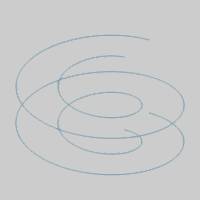
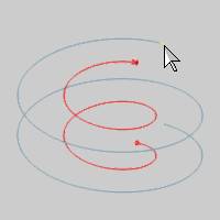
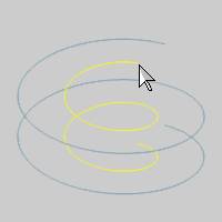
In the example file, the geometry for the ruled surface is two 3D spirals(helices) that consist of many line segments.Ruled Surface uses two wireframechains to create a surface with a linear connection between the chains.For the first part of this example we see the result of the spline curvesmade of line segments.
Part 2) Open Ruled Surface
- In the Advanced Surfaces group, of the Create 3D tab, click Ruled Surface.
The parameters display in the Data Entry Manager.
Part 3) Select Geometry
-
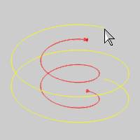
Press and hold Shiftand click the small line segment at the upper end of the helix.
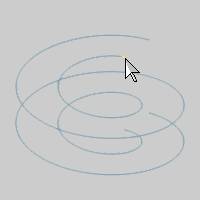
The start and end arrows display to show the first chain is selected. -
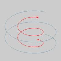
Chain select the second helix using the samemethod.Be sure to click near the upper end of the helix to definethe same chain direction as the first chain.
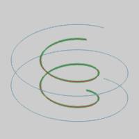
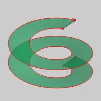
When you complete the second chain selection, the surface preview is automaticallycreated.
Notice the preview of the resulting surface is many small surfaces, one for each setof line segments in the two helices.
In order to create the surface as a single smooth surface, we use an Approximated Spline to create a single entity from each helix.
Part 4) Create Splines from Curves
-
In the LayersManager, right-click Splineand click Active Layer.
This is done so the splines are created on a separate layer from theoriginal helix geometry. -
In the Entity groupof the Create 2D ribbon, click the down arrow under
 Spline, and select
  Approximated.
 - In the Points From Mode group, of the Data Entry Manager, select the Multi-Picking option.
- Press and hold Shiftand click the small line segment at the upper end of the helix.
The preview of the spline appears. - Click OK to create the spline.
- Press and hold Shiftand click the small line segment at the upper end of the other helix.
The preview of the spline appears. - Click OK to create the spline.
-
To close the Data Entry Manager, click Cancel.
-
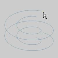
In the LayersManager, right-click Wireframeand click Hide to hide theoriginal helices.
Part 5) Edit the Ruled Surface Feature
- In the Advanced Surfaces group, of the Create 3D tab, click Ruled Surface.
-
Hover over the first spline, hold shift and left click to select the first chain.
- Hover over the second spline, hold shift and left click to select it as the second chain.
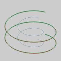
The second chain is added to the Selected Geometry list, and the preview is immediately visible. - Press OK to finalize the Ruled Surface.
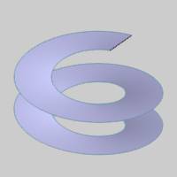
Notice the significant improvement in theRuled Surface as a result of creating the spline curves.The surface isnow a single entity.This method can often be used to improve the resultof a Ruled Surface when using complex wireframe input geometry, especiallywhen the chains don't contain the same number of entities.
This concludes the example.