


 Skin Surface
Introduction
This topic will explain the Skin Surface function, and the optionsfound in it.This topic will also describe where to find the function,provide quick steps and an example on how to use it, and provide links to related topics.
The Skin Surface Function
The Skin function is used to create a surface using two or more wireframechains as cross sections and two or more wireframe chains as rails.Tocreate the surface, you chain select the cross sections, which share thesame general direction, and then chain select the rails last, which alsoshare the same general direction.
Tip: Just like the Cross Section surface creation function, this Skin surface creation function can use many cross sections to set the shape of the surface.The Skin function, however, also has the added benefit of rail curves to guide surface creation even further.
Navigation
To open Skin Surface:
-
In the Advanced Surfacesgroup, of the Create 3D tab, click
 Skin Surface.
The parameters display in the Data Entry Manager.
The Data Entry Parameters
-
 Preview - Select the check box to enable the CAD preview, which displays what the result will be before you create it. Once all geometry is selected, the preview is shown.
  Preview - Clear the check box
to turn off the CAD preview.
Preview - Clear the check box
to turn off the CAD preview.
Cross Section Curves
|
|
|
| The list box will list the entities currently selected for the function. | |
 (Delete All)
- removes all entities from the Selected Geometry list.
(Delete All)
- removes all entities from the Selected Geometry list.Rail Curves
|
|
|
| The list box will list the entities currently selected for the function. | |
|---|---|
- OK - finalizes the function.
- Cancel - exits the function.
Quick Steps - Skin Surface
When creating Skin Surface, you chain select each of the cross sectionsand rails.Each chain can be one or more entities.Select the cross sectionsso they share a direction and select the rails so they share a direction.
-
Open the function.
-
Chain select the first Cross Section Curve.
The chain is added to the Cross Section Curves list.
Tip: To chainselect an entire chain, hold Shiftand click near the end of the last entity to set the start and end ofthe chain in one click.To select a portion of a chain, click near theend of the first chain entity to set the start of the chain, then hold Shift and click near the end ofthe last entity to set the end of the chain.
-
Chain select the second Cross Section Curve in the same generaldirection as the first.
The chain is added to the Cross Section Curves list. -
Repeat this process for the two rails.
The Preview displays once a surface can be created. -
To finalize the surface, click OK inthe Data Entry Manager.
The feature is added to the CAD Tree.
You can repeat this process for any other surfaces. -
To close the function, click Cancel.
Example
Note: In theimages below, both the Show Axis X-Yand Show Gnomon toggles have beendisabled in the Axis X-Y groupof the Settings Part > Displaydialog.
-
In the Quick Access Toolbar, click
 Open.
Open. -
In the Opendialog box, navigate to C:\BobCAD-CAMData\BobCAD-CAM V**\Examples.
Note: This isthe default install location.If you performed a custom install, navigateto the location in which you installed the software.
-
Select Skin Surface Example,and click Open.
The file opens.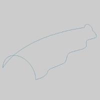
Leave the file in the ISO 2 view. -
In the Advanced Surfacesgroup, of the Create 3D tab, click
Skin Surface.
The Skin Surface parameters display in the Data Entry Manager and the Cross Section Curves list is given focus to acceptselection of chains. -
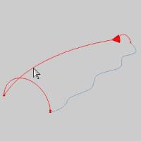
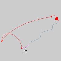
The first step is to select a chain to assign as a Cross SectionCurve.
Highlight the entity as seen in the image below.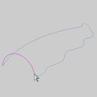
-
Click the entity to set the start of the chain.
-
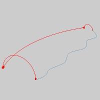
Highlight the end of the chain, which, for this cross section,can be the same position.
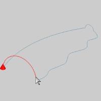
-
Press and hold Shift onthe end of the entity to setthe end of the chain.
The chain is added to the Cross Section Curves list.
Tip: Whileselecting the geometry for a cross section, you can click the start arrowto change the direction of that cross section, or use the Reverse buttonafter highlighting that chain in the Selected Geometry list of the CrossSection Surface parameters in the Data Entry Manager.It is importantthat all of the cross sections share the same direction.
-
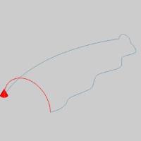
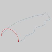
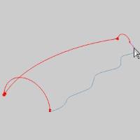
Hover over the end of the next Cross Section, as seen in theimage below.
-
Click the entity to set the start of the chain.
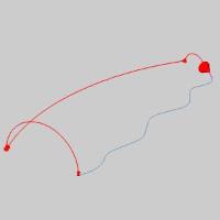
Highlight the end of the chain, which, for this cross section, canbe the same position.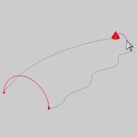
-
Press and hold Shift onthe end of the entity to setthe end of the chain.
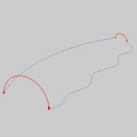
The chain is added to the Cross Section Curves list. - In the Data Entry Manager, click in the Rail Curves list to give it focus.
-
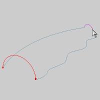
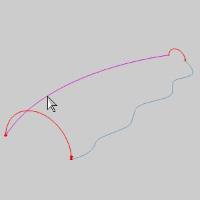
Hover over the end of the first Rail, as seen in the image below.
-
Click the entity to set the start of the chain.
-
Highlight the end of the chain, which, for this rail curve,can be the same position.
-
Press and hold Shift onthe end of the entity to setthe end of the chain.
The chain is added to the Rail Curves list. -
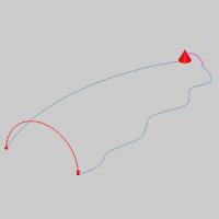
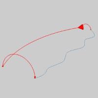
The second rail is the first of our chains that is comprisedof several entities.Hover over the end of the first entity of thesecond Rail, as seen in the image below.
-
Click the entity to set the start of the chain.
-
Highlight the end of the last entity of the chain, as seen inthe image below.
-
Press and hold Shift onthe end of the entity to setthe end of the chain.
The chain is added to the Rail Curves list.
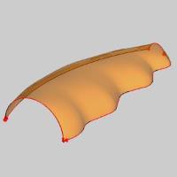
Now, with enough Cross Sections Curves and Rail Curves to create asurface, the Preview appears. -
Click OK to finalizethe Skin.
The surface is created in the graphics area and a Skinfeature is created in the  CAD Tree.
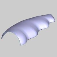
-
To end the function, click Cancel.
This concludes the example.