


 Break Surface
Introduction
This topic will explain the Break Surface function, and the optionsfound in it.This topic will also describe where to find the function,provide quick steps and an example on how to use it, and provide links to related topics.
The Break Surface Function
The Break Surfaces function is used to modify or break a surface, usinga wireframe curve that is on the surface.To perform the function, youfirst select the surface, then select the curve, and press the Spacebarto confirm the selection.The surface is broken at the curve when youconfirm the selection.

Tip: Youcan create the wireframe curve directly on the surface, or you can usethe Project Curves to Surface function if your curve is not already onthe surface (and it is above or below it).Otherwise, you can use theTranslate function to move the geometry onto the surface before usingthe Break Surfaces function.
Navigation
To open Break Surface:
-
In the Modifygroup, of the Create 3D tab, click
 Break Surface.
The parameters display in the Data Entry Manager.
The Data Entry Parameters
Surface/Solid to Break
|
|
|
| The list box will list the entity currently selected for the function. | |
Breaking Curves (need to be on the surface)
|
|
|
| This list box will show the entities currently selected for the function. | |
 (Delete All)- removes all entities from the list.
- OK - finalizes the function.
- Cancel - exits the function.
Quick Steps - Break Surface
Be sure that the break curve (wireframe) is on the surface that youwant to break.
-
Open the function.
The Surface/Solid to Break list automatically has focus to allow youto add entities to it. -
Click to select the surface that you wantto break.
The selection does not require confirmation, as you can only selecta single surface, or solid.
Once selected, the focus shifts to the Breaking Curves list. -
Click to select the wireframe chain thatdefines where the surface is broken.
Tip: It canbe helpful to turn off shading to make it easier to select the wireframecurve that is on the surface.In the View menu, click Shaded, or you canpress S to toggle the shaded view.You can also place the wireframe on another layer and use Select by Layer.
-
After selecting the wireframe breaking chain, confirm the selectionsby pressing Spacebar, or by clicking OK.
The surface/solid is broken into multiple surfaces when you confirmthe selection.
The feature is added to the CAD Tree. -
Repeat this process as needed to break any other surfaces.
-
To close the function, click Cancel.
Example
This example will demonstrate how to use the 4 Edge function.
Note: In theimages below, both the Show Axis X-Yand Show Gnomon toggles have beendisabled in the Axis X-Y groupof the Settings Part > Displaydialog.
-
In the Quick Access Toolbar, click
 New.
New.
A New window opens. -
Enter into an ISO2 view by pressing Ctrl+7.
-
In the Surfaces group, of the Create 3D ribbon,click the down arrow under
 Planar, and select
  Rectangular Plane.
The Rectangular Plane parameters display in the Data Entry Manager. -
In the Corner Type group, click
 to use filleted corners.
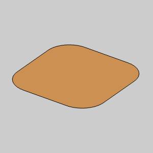
-
Click OK toconfirm the size and location of the Rectangular Plane.
The Rectangular Plane is created in the graphics area and aRectangularPlane feature is created in the  CADTree.
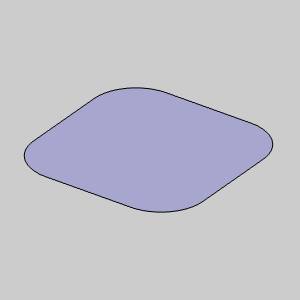
-
In the Entity group, of the Create 2D ribbon, click the down arrow under
 Arc, and select
  Arc Center.
The Arc Coordinate parameters display in the Data Entry Manager.
The Preview appears.
-
Change the Radiusvalue to 0.5000.
The Preview updates.
-
Click OK toconfirm the arc.
The arc is created.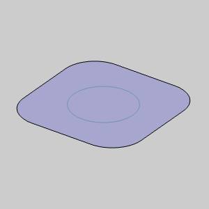
-
In the Modifygroup, of the Create 3D tab, click
Break Surface.
The Break Surface parameters display in the Data Entry Manager.
The Surface/Solid to Break list is automatically given focus to allowselection of the surface or solid to break. -
Hover over the Rectangular Plane as seen in the imagebelow.
-
Click the Rectangular Plane to add it to the Surface/Solidto Break list.
The Rectangular Plane is added to the Surface/Solid to Break list.
The focus is automatically shifted to the Breaking Curves list to allowyou select the entities that will define the area of the break.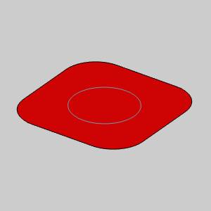
-
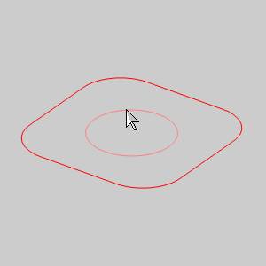
Press S toturn toggle the
 Shaded view.
The shading is removed from the Rectangular Plane.
Tip: With theShaded view turned off, the surfaces or solids can only be selected byclicking on one of its edges.This allows us to select geometrythat may be on, inside, or behind the surfaces or solids.
-
Hover over the arc as seen in the image below.
-
Click the arc to add it to the BreakingCurves list.

-
Press S to turntoggle the
Shadedview.
The shading is added to the Rectangular Plane.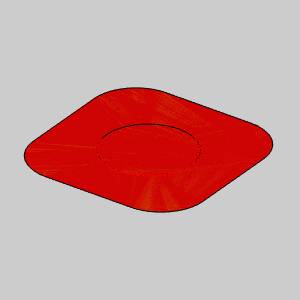
-
Click OK to confirm the break.
The surface is broken, and a Break Surface feature is addedto the CADTree.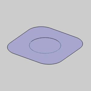
-
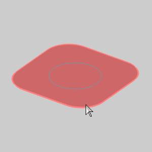
Hover of the Rectangular Plane as seen in the image below.
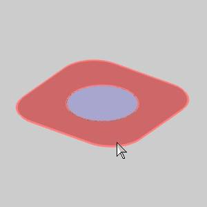
Notice there are now two separate surfaces. -
To end the function, click Cancel.
This concludes the example.