


 Boolean
Introduction
This topic will explain the Boolean function, will explain whereto find the function, and explain the options found in it.This topicwill also explain creation with quick steps and examples, and provide links to relatedtopics.
The Boolean Functions
The Boolean function gives you access to several functions; Add, Subtract,and Intersect.Each of these options provide a different way to handlethe interaction between solids and surfaces.This topic explains eachof the functions.

|

|

|
|
Joins two or more solids or surfaces together. |
Removes the intersecting area of one solid or surface from another. |
Keeps only the overlapping portion of all the selected entities as a single solid. |
Navigation
To open Boolean, do one of the following:
- In the Solid Boolean group, of the Create 3D ribbon, click the
 Boolean.
 - In the Solid Boolean group, of the Create 3D ribbon, click the down arrow under Boolean, and select:
- Add
 Subtract
 Intersect
The Boolean parameters display in the Data Entry Manager.
Note: Whether you click the main icon, or the down arrow to get to the other options, you will have access to the same options in the Data Entry Manager.
The Data Entry Parameters
 Type
Type
![]() Add - TheAdd function joins two or more solids or surfaces together in a booleanoperation.To perform the function, you select the entities in any order,and then press the Spacebar to confirm the selections.After performingthe function, the entities can then be selected as a single entity.
Add - TheAdd function joins two or more solids or surfaces together in a booleanoperation.To perform the function, you select the entities in any order,and then press the Spacebar to confirm the selections.After performingthe function, the entities can then be selected as a single entity.
|
Solid/Surface Bodies to Union Together |
|
|
|
|
| The Solid/Surface Bodies to Union Together list box will list the entities currently selected for the function to add togehter. | |
 (Delete All)- removes all entities from the Selected Geometry list.
![]() Subtract - TheSubtract function removes the intersecting area of one solid or surfacefrom another in a boolean operation.You can select any number of solidor surface entities for the function, but the first selection must bethe entity that you want to keep and the entities must intersect eachother.
Subtract - TheSubtract function removes the intersecting area of one solid or surfacefrom another in a boolean operation.You can select any number of solidor surface entities for the function, but the first selection must bethe entity that you want to keep and the entities must intersect eachother.
|
Main Solid/Surface Body |
|
|
|
|
| The Main Solid/Surface Body list box will list the entities currently selected for the function to subtract from. | |
|
Solid/Surface Bodies to Subtract |
|
|
|
|
| The Solid/Surface Bodies to Subtract list box will list the entities currently selected for the function to subtract. | |
![]() Intersect - TheIntersect function is a boolean operation that combines two or more solidsor surfaces keeping only the overlapping portion of both as a single solid.You can select more than two surfaces or solids when using this function.To perform the function, you select the entities in any order, and thenpress the Spacebar to confirm the selections.
Intersect - TheIntersect function is a boolean operation that combines two or more solidsor surfaces keeping only the overlapping portion of both as a single solid.You can select more than two surfaces or solids when using this function.To perform the function, you select the entities in any order, and thenpress the Spacebar to confirm the selections.
Important: Thisfunction finds the intersection of allthe selected solids/surfaces.It does not find allintersections.For instance, if each selected entity does not intersectall other selected entities, nothing will be kept.
|
Solid/Surface Bodies to Intersect |
|
|
|
|
| The Solid/Surface Bodies to Intersect list box will list the entities currently selected for the function to add togehter. | |
- Show Preview / Hide Preview
Once geometry has been added to the SelectedGeometry list, selecting this toggle will enable, and disable the CADpreview, which displays the result that will be created when you clickOK.
- OK - performs the functionafter geometry selection.
- Cancel - cancels the functionwhen finished.
Quick Steps
Quick Steps - Boolean Add
-
Open the function.
Focus is automatically on the Solid/Surface Bodies to Union Togetherlist. -
Select all solid or surface entities thatyou want to add together into a single solid entity.The order ofthe selection does not matter.
-
You can press Spacebar, click
 , or click OK in the DataEntry tab to confirm the selections.
The feature is added to the CAD Tree.
The entities are added and can now be selected as a single entity.
You can repeat this process as many times as needed. -
To close the function when you are finished,click Cancel.
Quick Steps - Boolean Subtract
-
Open the function.
Focus is automatically on the Main Solid/Surface Body list. -
Select the solid or surface a portion isbeing removed from.
Once an entity is added to the Main Solid/Surface Body list, focusis automatically shifted to the Solid/Surface Bodies to Subtract list. -
Select the solids or surface bodies to subtract.
-
Click Show Preview, to see a preview of theend result.
-
You can press Spacebar, click
, or click OK in the DataEntry tab to confirm the selections.
The feature is added to the CAD Tree.
The entities are subtracted, and the remainder of the Main Solid/SurfaceBody is left.
You can repeat this process as many times as needed. -
To close the function when you are finished,click Cancel.
Quick Steps - Boolean Intersect
-
Open the function.
Focus is automatically on the Solid/Surface Bodies to Intersect list. -
Select the intersecting solids or surfaces.
-
Click Show Preview, to see a preview of theend result.
-
You can press Spacebar, click
, or click OK in the DataEntry tab to confirm the selections.
The feature is added to the CAD Tree.
The intersection of the selected entities is left.
You can repeat this process as many times as needed. -
To close the function when you are finished,click Cancel.
Examples
Example Boolean Add
This example will demonstrate how to use the Boolean Add function.
Note: In theimages below, both the Show Axis X-Yand Show Gnomon toggles have beendisabled in the Axis X-Y groupof the Settings Part > Displaydialog.
-
In the Quick Access Toolbar, click
 New.
New.
A new document opens. -
Enter into an ISO2 view by pressing Ctrl+7.
-
In the Primitives group, of the Create 3D tab, click
 Cube.
Cube.
The Cube parameters display in the Data Entry Manager.
The Preview appears.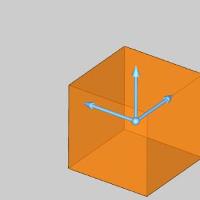
-
The first cube being created will be left at the defaultsize, and location.
Click OK to confirm the firstcube.
The Cube is created in the graphics area and a Cube feature is created inthe
  CADTree.
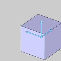
-
In the Origingroup, change the values to X-1.0000,Y1.0000, Z1.0000.
The Preview updates.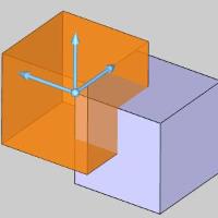
-
Click OK toconfirm the second cube.
The Cube is created in the graphics area and anotherCubefeature is created in the CAD Tree.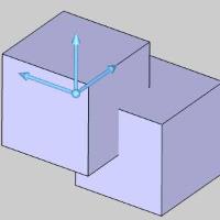
-
In the Corners group, of the Create 3D tab, click
 Solid Fillet.
The Solid Fillet parameters display in the Data Entry Manager. -
In the Solid Fillet parameters, click WholeSolid.
This will allow us to apply the fillet to every edge of the solid atonce. -
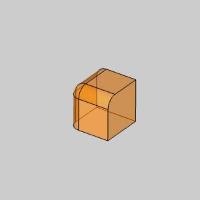
Hover over the first cube as seen in the image below.
-
Click the cube to select it.
The cube is selected.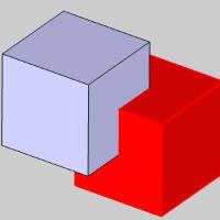
-
Click OK toconfirm the fillet.
The fillet is created and a SolidFilletfeature is created in the CAD Tree.
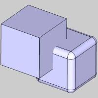
-
In the Solid Boolean group, of the Create 3D ribbon, click the down arrow under
Boolean, and select Add.
The Boolean parameters display in the Data Entry Manager.
Add is automatically selected as the function in use.
The Solid/Surface Bodies to Union Together list is automatically givenfocus to allow selection of the surfaces or solids to combine. -
Hover over the first cube as seen in the image below.
-
Click the cube to add it to the Surface/Solid to UnionTogether list.
The cube is selected, and is added to the Solid/Surface Bodies to UnionTogether list.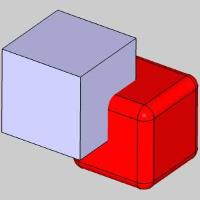
-
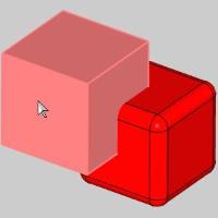
Hover over the second cube as seen in the image below.
-
Click the cube to add it to the Surface/Solid to UnionTogether list.
The cube is selected, and is added to the Solid/Surface Bodies to UnionTogether list.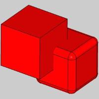
-
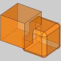
Click Show Previewto see a preview of the end result.
-
Click the OKto finalize the result.
The two cubes are added together and a Booleanfeature is created in the CAD Tree.
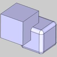
-
Hover over either cube.
With the cubes added together, the newly created solid highlights asone.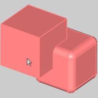
-
To end the function, click Cancel.
This concludes the example.
Example Boolean Subtract
This example will demonstrate how to use the Boolean Subtract function.
Note: In theimages below, both the Show Axis X-Yand Show Gnomon toggles have beendisabled in the Axis X-Y groupof the Settings Part > Displaydialog.
-
In the Quick Access Toolbar, click
New.
A new document opens. -
Enter into an ISO2 view by pressing Ctrl+7.
-
In the Primitives group, of the Create 3D tab, click
Cube.
The Cube parameters display in the Data Entry Manager.
The Preview appears. -
The first cube being created will be left at the defaultsize, and location.
Click OK to confirm the firstcube.
The Cube is created in the graphics area and aCube feature is created inthe CADTree. -
In the Origingroup, change the values to X-1.0000,Y1.0000, Z1.0000.
The Preview updates. -
Click OK toconfirm the second cube.
The Cube is created in the graphics area and anotherCubefeature is created in the CAD Tree. -
In the Corners group, of the Create 3D tab, click
Solid Fillet.
The Solid Fillet parameters display in the Data Entry Manager. -
In the Solid Fillet parameters, click WholeSolid.
This will allow us to apply the fillet to every edge of the solid atonce. -
Hover over the first cube as seen in the image below.
-
Click the cube to select it.
The cube is selected. -
Click OK toconfirm the fillet.
The fillet is created and aSolidFilletfeature is created in the CAD Tree. -
In the Solid Boolean group, of the Create 3D ribbon, click the down arrow under
Boolean, and select Subtract.
The Boolean parameters display in the Data Entry Manager.
Subtract is automatically selected as the function in use.
The Main Solid/Surface Body list is automatically given focus to allowselection of the main surfaces or solids to subtract from. -
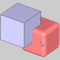
Hover over the first cube as seen in the image below.
-
Click the cube to add it to the Main Solid/SurfaceBody list.
The cube is selected, and is added to the Main Solid/Surface Body list.
Focus is automatically shifted to the Solid/Surface Bodies to Subtractlist to allow us to add solids and surface bodies to delete from themain body. -
Hover over the second cube as seen in the image below.
-
Click the cube to add it to the Solid/Surface Bodiesto Subtract list.
The cube is selected, and is added to the Solid/Surface Bodies to Subtractlist. -
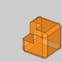
Click Show Previewto see a preview of the end result.
-
Click the OKto finalize the result.
The intersecting portion of the two cubes is removed from the mainbody, and a Boolean feature is created in theCADTree.
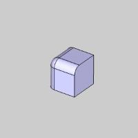
-
To end the function, click Cancel.
This concludes the example.
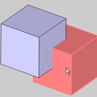
Example Boolean Intersect
This example will demonstrate how to use the Boolean Intersect function.
Note: In theimages below, both the Show Axis X-Yand Show Gnomon toggles have beendisabled in the Axis X-Y groupof the Settings Part > Displaydialog.
-
In the Quick Access Toolbar, click
New.
A new document opens. -
Enter into an ISO2 view by pressing Ctrl+7.
-
In the Primitives group, of the Create 3D tab, click
Cube.
The Cube parameters display in the Data Entry Manager.
The Preview appears. -
The first cube being created will be left at the defaultsize, and location.
Click OK to confirm the firstcube.
The Cube is created in the graphics area and aCube feature is created inthe CADTree. -
In the Origingroup, change the values to X-1.0000,Y1.0000, Z1.0000.
The Preview updates. -
Click OK toconfirm the second cube.
The Cube is created in the graphics area and anotherCubefeature is created in the CAD Tree. -
In the Corners group, of the Create 3D tab, click
Solid Fillet.
The Solid Fillet parameters display in the Data Entry Manager. -
In the Solid Fillet parameters, click WholeSolid.
This will allow us to apply the fillet to every edge of the solid atonce. -
Hover over the first cube as seen in the image below.
-
Click the cube to select it.
The cube is selected. -
Click OK toconfirm the fillet.
The fillet is created and aSolidFilletfeature is created in the CAD Tree. -
In the Solid Boolean group, of the Create 3D ribbon, click the down arrow under
Boolean, and select Intersect.
The Boolean parameters display in the Data Entry Manager.
Intersect is automatically selected as the function in use.
The Solid/Surface Bodies to Intersect list is automatically given focusto allow selection of the surfaces or solids to find the intersectionbetween. -
Hover over the first cube as seen in the image below.
-
Click the cube to add it to the Surface/Solid Bodiesto Intersect list.
The cube is selected, and is added to the Solid/Surface Bodies to Intersectlist. -
Hover over the second cube as seen in the image below.
-
Click the cube to add it to the Surface/Solid to Intersectlist.
The cube is selected, and is added to the Solid/Surface Bodies to Intersectlist. -
Click Show Previewto see a preview of the end result.
-
Click the OKto finalize the result.
The intersecting portion of the two cubes are all that remains in thegraphics area, and a Boolean feature is createdin the CADTree.
 -
To end the function, click Cancel.
This concludes the example.