


 3 Edge Surface
Introduction
This topic will explain the 3 Edge Surface function, and the optionsfound in it.This topic will also describe where to find the function,provide quick steps and an example on how to use it, and provide links to related topics.
The 3 Edge Surface Function
The 3 Edge Surface function creates a 3-dimensional surface using 3connected edge curves.To perform the function, you chain select the threegeometry curves in the Workspace one at a time, and then press the Spacebarto confirm the selections.The direction of the selected chains controlthe outcome of the surface so the chains should follow the same direction.
Navigation
To open 3 Edge Surface:
-
In the Modifygroup, of the Create 3D tab, click
 3 Edge Surface.
The parameters display in the Data Entry Manager.
The Data Entry Parameters
-
 Preview - Select the check box to enable the CAD preview, which displays what the result will be before you create it. Once all geometry is selected, the preview is shown.
  Preview - Clear the check box
to turn off the CAD preview.
Preview - Clear the check box
to turn off the CAD preview.
Parameters
Selected Geometry
|
|
|
| This list box will show the entities currently selected for the function. | |
 (Delete All)- removes all entities from the list.
- OK - finalizes the function.
- Cancel - exits the function.
Quick Steps - 3 Edge Surface
When creating 3 Edge Surface, you chain select each of the three surfaceedges.Each chain can be one or more entities.The selection order determinesthe results, and the chains should all share the same general direction,such as clockwise.
- Open the function.
The Selected Geometry list automatically has focus. - Chain select the first chain.
- Chain select the remaining chains.
Once surface creation is possible, a preview will appear. - Use the controls next to the Selected Geometry list to adjust the direction of chains, the chains order in the list, and which chains are in the list.
- Click OK to create the surface.
The feature is added to the CAD Tree. - Repeat as necessary.
- Click Cancel to exit the function.
Example
This example will demonstrate how to use the 3 Edge function.
Note: In theimages below, both the Show Axis X-Yand Show Gnomon toggles have beendisabled in the Axis X-Y groupof the Settings Part > Displaydialog.
-
In the quick access toolbar, click
 Open.
Open. -
In the Opendialog box, navigate to C:\BobCAD-CAMData\BobCAD-CAM V**\Examples.
Note: This isthe default install location.If you performed a custom install, navigateto the location in which you installed the software.
-
Select 3 edge surface example.bbcd,and click Open.
The file opens.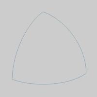
Leave the file in the ISO 2 view. -
In the Modifygroup, of the Create 3D tab, click
3 Edge Surface.
The 3 Edge Surface parameters display in the Data Entry Manager. -
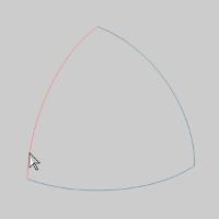
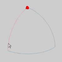
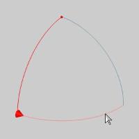
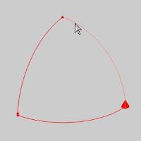
Highlight the end of the first entity, of the first chain, asseen in the image below.
Note: In thisexample, each chain is a single entity.If these chains were multipleentities, the steps would be the same; Click the end of the first entityof the first chain to set the start point and direction of the chain.Then hold Shift and click the end of the last entity of the first chainto set the end of the chain.Then repeat for the second and third chains.
-
Click the entity to set the start of the chain.
-
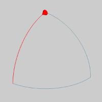
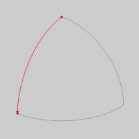
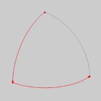
Highlight the end of the chain as seen in the image below.
-
Press and hold Shift onthe end of the entity to setthe end of the chain.
Tip: Whileselecting the geometry for a 3 Edge, you can click the start arrow tochange the direction of that cross section, or use the Reverse buttonafter highlighting that chain in the Selected Geometry list of the 3 EdgeSurface parameters in the Data Entry Manager.It is important that allof the chains share the same direction.
-
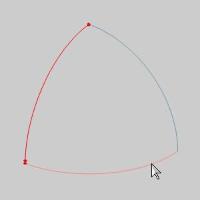
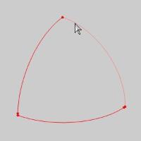
Hover over the end of the next chain, as seen in the image below.
-
Click the entity to set the start of the second chain.
-
Highlight the end of the chain as seen in the image below.
-
Press and hold Shift onthe end of the entity to setthe end of the chain.
-
Hover over the end of the next chain, as seen in the image below.
-
Click the entity to set the start of the second chain.
-
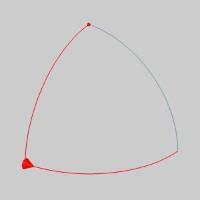
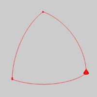
Highlight the end of the chain as seen in the image below.
-
Press and hold Shift onthe end of the entity to setthe end of the chain.
The Preview appears.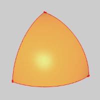
-
Click OK to finalizethe 3 Edge.
The surface is created and a 3 Edge feature is createdin the  CADTree.
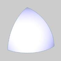
-
To end the function, click Cancel.
This concludes the example.