


 Cross-Section Surface
Introduction
This topic will explain the Cross-Section Surface function, and the optionsfound in it.This topic will also describe where to find the function,provide quick steps and an example on how to use it, and provide links to related topics.
The Cross-Section Surface Function
The Cross-Section Surface function createsa surface from a group of wireframe curves that are roughly parallel.To perform the function, you chain select each of the cross section entitiesone at a time, press the Spacebar to confirm the selection, and clickOK.You can have as many cross sections as you like, but you must haveat least two.The order in which you select the cross sections determineshow the surface is created.
Navigation
To open Cross-Section:
-
In the Surfacesgroup, of the Create 3D tab, click
 Cross-Section.
The parameters display in the Data Entry Manager.
The Data Entry Parameters
-
 Preview - Select the check box to enable the CAD preview, which displays what the result will be before you create it. Once all geometry is selected, the preview is shown.
  Preview - Clear the check box
to turn off the CAD preview.
Preview - Clear the check box
to turn off the CAD preview.
Selected Geometry
|
|
|
| This list box will show the entities currently selected for the function. | |
 (Delete All)- removes all entities from the list.
- OK - finalizes the function.
- Cancel - exits the function.
Quick Steps - Cross-Section
When creating a Cross-Section Surface, you complete one chain selectionfor each cross section.Each chain can be one or more entities.The selectionorder determines the results, and the chains should all share the samegeneral direction, such as left to right.
-
Open the function.
The Selected Geometry list automatically has focus. -
Chain select the first chain.
Tip: To chainselect an entire chain, hold Shiftand click near the end of the last entity to set the start and end ofthe chain in one click.To select a portion of a chain, click near theend of the first chain entity to set the start of the chain, then holdShift and click near the end ofthe last entity to set the end of the chain.
-
Chain select the second chain using the same direction as thefirst chain.
With two chains selected, the Preview appears. -
Repeat this process until all cross sections of the surfaceare selected and using the same direction.
The Preview updates with every new cross section added to the SelectedGeometry list. -
To create the surface, in the Data Entry Manager, click OK.
The feature is added to the CAD Tree.
You can repeat this process for any other surfaces. -
To close the function, click Cancel.
Example
This example will demonstrate how to use the Cross Section function.
Note: In theimages below, both the Show Axis X-Yand Show Gnomon toggles have beendisabled in the Axis X-Y groupof the Settings Part > Displaydialog.
-
In the quick access toolbar, click
 Open.
Open. -
In the Opendialog box, navigate to C:\BobCAD-CAMData\BobCAD-CAM V**\Examples.
Note: This isthe default install location.If you performed a custom install, navigateto the location in which you installed the software.
-
Select cross section surfaceexample.bbcd, and click Open.
The file opens.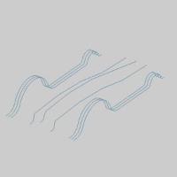
Leave the file in the ISO 2 view. -
In the Surfacesgroup, of the Create 3D tab, click
Cross-Section.
The Cross Section Surface parameters display in the Data Entry Manager. -
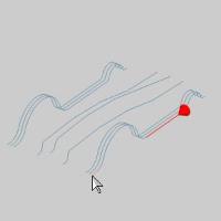
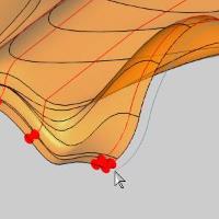
Highlight the entity as seen in the image below.
-
Click the entity to set the start of the chain.
-
Highlight the end of the chain as seen in the image below.
-
Press and hold Shift onthe end of the entity to setthe end of the chain.
Tip: To chainselect a portion of a chain, as we have done here, click near the endof the first chain entity to set the start of the chain, then hold Shift and click near the end ofthe last entity to set the end of the chain.To select an entire chainat once, hold Shift and clicknear the end of the last entity to set the start and end of the chainin one click.
Tip: Whileselecting the geometry for a cross-section, you can click the start arrowto change the direction of that cross section, or use the Reverse buttonafter highlighting that chain in the Selected Geometry list of the CrossSection Surface parameters in the Data Entry Manager.It is importantthat all of the cross sections share the same direction.
-
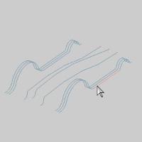
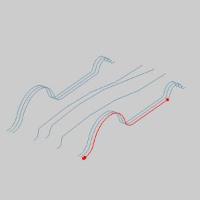
Hover over the end of the next chain, as seen in the image below.
-
Press and hold Shift,and click the end of the entity to chain select the entire chain.
With two cross sections added to the Selected Geometry list, the Previewdisplays.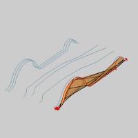
-
Repeat step 11 for each of the subsequent chains, in order,until all are added to the Selected Geometry list.

Notice the difference between the two sides.Even though the last fourchains are mirror images of the first four chains, selecting onlya portion of the first chain, as we have done, has created some irregularities.We will correct that in the next steps. -
In the Selected Geometry list, click on Chain-1to highlight it.
The chain highlights in the graphics area.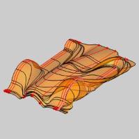
-
Click
 (Delete)to remove the partial chain from the list.
Tip: You canalso right-click a chain in the list to gain access to the same controlsseen on the buttons.
The Preview updates.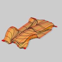
-
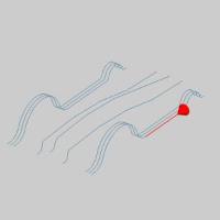
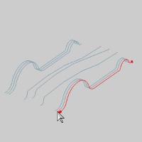
Hover over the end of the deselected chain as seen in the imagebelow.
-
Press and hold Shift,and click the end of the entity to chain select the entire chain.
The chain is added to the Selected Geometry list as Chain-10 and thePreview updates.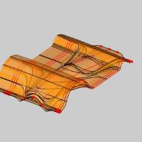
Because the order of the chains in the Selected Geometry list is wrong,the Preview show an unintended result.We will correct that in thenext steps. -
In the Selected Geometry list, click Chain-10to highlight it.
The chain highlights in the graphics area.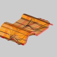
-
Click the
 (Move Up) button to move Chain-10 up the list.
The Preview updates.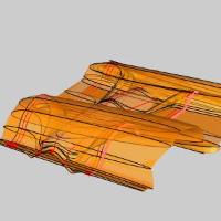
The order is still off.We need to move Chain-10 to the top of thelist. -
Click the
(Move Up) button to move Chain-10 up the list, until it is at thetop of the list.
The Preview updates.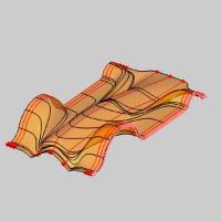
-
Click OK to finalizethe Cross Section.
The surface is created and aCross Section feature is createdin the  CADTree.
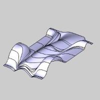
-
To end the function, click Cancel.
This concludes the example.