


 Multisided Patch
Introduction
This topic will explain the Multisided Patch function, will explain whereto find the function, and explain the options found in it.This topicwill also explain creation with quick steps and examples, and provide links to relatedtopics.
The Multisided Patch Function
The Multisided Patch function is used to create a 3-dimensional surfacefrom a closed chain that consists of 3 or more edge curves.To performthe function, you chain select each geometry curve one at a time in aconsecutive order.After the chain direction of all edge curves is defined,you confirm the selection to create the surface.
Navigation
To open Multisided Patch:
- In the Surfaces group, of the Create 3D tab, click
 Multisided Patch.
The parameters display in theData Entry Manager.
The Data Entry Parameters
-
 Preview - Select the check box to enable the CAD preview, which displays what the result will be before you create it. Once all geometry is selected, the preview is shown.
  Preview - Clear the check box
to turn off the CAD preview.
Preview - Clear the check box
to turn off the CAD preview.
Selected Geometry
|
|
|
| This list box will show the entities currently selected for the function. | |
 (Delete All)- removes all entities from the list.
- OK - finalizes the function.
- Cancel - exits the function.
Quick Steps - Multisided Patch
When creating a Multisided Patch, you complete one chain selection foreach side of the surface.Each chain can be one or more entities.Theselection order determines the results, and the chains should all sharethe same general direction, such as clockwise.
- Open the function.
The Selected Geometry list automatically has focus. - Chain select the first chain.
- Chain select the remaining chains.
Once surface creation is possible, a preview will appear. - Use the controls next to the Selected Geometry list to adjust the direction of chains, the chains order in the list, and which chains are in the list.
- Click OK to create the surface.
The feature is added to the CAD Tree. - Repeat as necessary.
- Click Cancel to exit the function.
Example 1
This example will demonstrate how to use the Multisided Patch function.
Note: In theimages below, both the Show Axis X-Yand Show Gnomon toggles have beendisabled in the Axis X-Y groupof the Settings Part > Displaydialog.
-
In the Quick Access Toolbar, click
 Open.
Open. -
In the Opendialog box, navigate to C:\BobCAD-CAMData\BobCAD-CAM V**\Examples.
Note: This isthe default install location.If you performed a custom install, navigateto the location in which you installed the software.
-
Select multisided patch surfaceexample.bbcd, and click Open.
The file opens.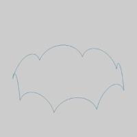
Leave the file in the ISO 2 view. -
In the Surfaces group, of the Create 3D tab, click
Multisided Patch.
The Multisided Patch parameters display in the Data Entry Manager. -
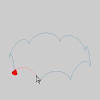
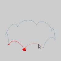
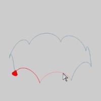
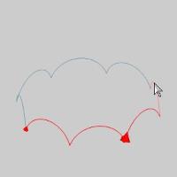
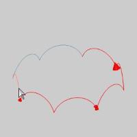
Highlight the end of the first entity, of the first chain, asseen in the image below.
Note: In thisexample, each chain is a single entity.If these chains were multipleentities, the steps would be the same; Click the end of the first entityof the first chain to set the start point and direction of the chain.Then hold Shift and click the end of the last entity of the first chainto set the end of the chain.Then repeat for the second and third chains.
-
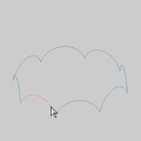
Click the entity to set the start of the chain.
-
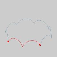
Highlight the end of the first chain as seen in the image below.
-
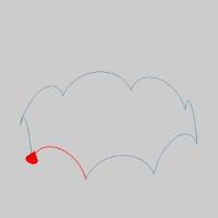
Press and hold Shift onthe end of the entity to setthe end of the chain.
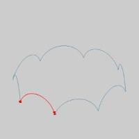
The chain is added to the Selected Geometry list.
Tip: Whileselecting the geometry for a Multisided Patch, you can click the startarrow to change the direction of that cross section, or use the Reversebutton after highlighting that chain in the Selected Geometry list ofthe Multisided Patch Surface parameters in the Data Entry Manager.Itis important that all of the chains share the same direction.
-
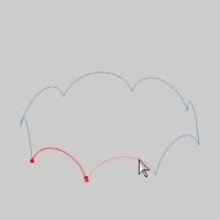
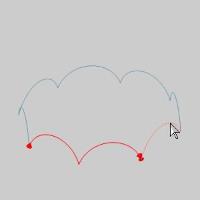
Hover over the end of the next chain, as seen in the image below.
-
Click the entity to set the start of the second chain.
-
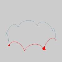
Highlight the end of the chain as seen in the image below.
-
Press and hold Shift onthe end of the entity to setthe end of the chain.
The second chain is added to the Selected Geometry list. -
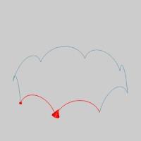
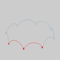
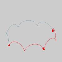
Continue with these steps, selecting each entity as an individualchain, until all chains are added to the Selected Geometry list.
With all chains selected the Previewappears.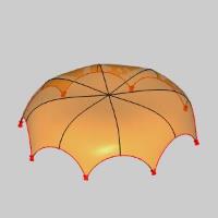
-
Click OK to finalizethe Multisided Patch.
The surface is created in the graphics area and a Multisided Patch feature iscreated in the  CAD Tree.
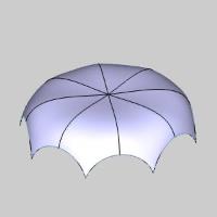
-
To end the function, click Cancel.
This concludes the example.
Example 2
This example will demonstrate how to achieve a different result withthe Multisided Patch function using the same geometry.
-
Press Ctrl+Zto undo the Multisided Patch Surface completed in Example 1.
-
In the Surfaces group, of the Create 3D tab, click
Multisided Patch.
The Multisided Patch parameters display in the Data Entry Manager. -
Highlight the end of the first entity, ofthe first chain, as seen in the image below.
-
Click the entity to set the start of thechain.
-
Highlight the end of the second entity asseen in the image below.
-
Press and hold Shifton the end of the entityto set the end of the chain.
The first chain is added to the Selected Geometry list.
Tip: Whileselecting the geometry for a Multisided Patch, you can click the startarrow to change the direction of that cross section, or use the Reversebutton after highlighting that chain in the Selected Geometry list ofthe Multisided Patch Surface parameters in the Data Entry Manager.Itis important that all of the chains share the same direction.
-
Hover over the end of the next entity, as seen in the imagebelow.
-
Click the entity to set the start of the second chain.
-
Highlight the end of the following entity as seen in the imagebelow.
-
Press and hold Shift onthe end of the entity to setthe end of the chain.
The second chain is added to the Selected Geometry list. -
The remaining entities will be selected as a single chain.
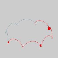
Hover over the end of the next entity as seen in the image below.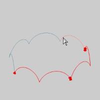
-
Press and hold Shift onthe end of the entity to setthe start of the chain.
-
Hover over the end of the last entity as seen in the image below.
-
Press and hold Shift onthe end of the entity to setthe start of the chain.
The third chain is added to the Selected Geometry list, and the preview appears.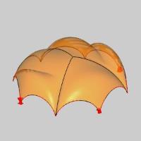
Note: As youcan see, using the same geometry, but defining the selected chains differently,can significantly alter the results.If we were to break the arcs, wecould adjust the selected chains, and therefore the results, even further.Keep this in mind when using this feature in the future.
-
Click OK to finalizethe Multisided Patch.
The surface is created in the graphics area and a Multisided Patch feature iscreated in the CAD Tree.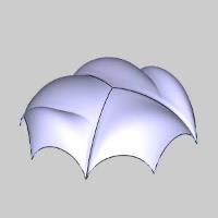
-
To end the function, click Cancel.
This concludes the example.