


 Revolve Surface
Introduction
This topic will explain the Revolve Surface function, will explain whereto find the function, and explain the options found in it.This topicwill also explain creation with quick steps and examples, and provide links to relatedtopics.
The Revolve Surface Function
The Revolve function creates a revolved surface from a 2D geometry chainbased on the settings that you define in the Data Entry Manager.To performthe function, you chain select the curve to revolve, and confirm the selectionto create the CAD preview.You then click OK to create the surface asshown in the CAD preview.When the CAD preview is turned off, the surfaceis created when you confirm the selection.

Navigation
To open Revolve Surface:
-
In the Surfaces group, of the Create 3D ribbon, click
 Revolve Surface.
The parameters display in the Data Entry Manager.
The Data Entry Parameters
-
 Preview - Select the check box to enable the CAD preview, which displays what the result will be before you create it. Once all geometry is selected, the preview is shown.
  Preview - Clear the check box
to turn off the CAD preview.
Preview - Clear the check box
to turn off the CAD preview.
|
|
|
|
|
|
Revolve Curve
|
|
|
| The list box will list the entity currently selected for the function. | |
- Rotation Angle - definesthe amount of rotation around the axis the selected geometry is tobe revolved.
90°
180°
270°
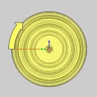
360°
-
With Caps- creates surfaces on the top and bottomof the extruded curve, thus making a solid.With Caps - omits the top and bottom surface of the extruded curve and creates a hollow shell.
|
|
|
|
|
|
Axis
-
Pick Axis - the axis will be defined manually, with an existing axis, or a defined vector.Pick Axis - the axis will be defined by selecting a line, or surface edge.
The following parameters vary depending on the Pick Axis option that is chosen:
![]() Pick Axis
Pick Axis
- Along X Axis - sets the X axis as the axis to revolve around.
- Along Y Axis - sets the Y axis as the axis to revolve around.
- Along Z Axis - sets the Z axis as the axis to revolve around.
- Customized Axis - allows for a custom axis to used for the axis to revolve around.
![]() Pick Axis
Pick Axis
Rotation Axis
|
|
|
| The list box will list the entity currently selected for the function. | |
Note: The direction definesthe vector of the rotation.The direction values are always visible, but can only be edited when Pick Axis is not selected, and the Customized Axis option is chosen.When it is, type in the desired values in the X,Y, Z boxes to define the direction from the Origin Point.
- Origin X - sets the X value for the center of rotation.
- Origin Y - sets the Y value for the center of rotation.
- Origin Z - sets the Z value for the center of rotation.
|
Geometry |
X0, Y0, Z0 |
X0,Y-1, Z0 |
X0,Y-1, Z1 |
|
|
|
|
|
- Direction X - lists the x value for the vector of the rotational axis.
- Direction Y - lists the y value for the vector of the rotational axis.
- Direction Z - lists the z value for the vector of the rotational axis.
|
DirectionX1, Y0, Z0 |
DirectionX0, Y1, Z0 |
Direction X0, Y0, Z1 |
|
|
|
|
- OK - finalizes the function.
- Cancel - exits the function.
Quick Steps - Revolve Surface
- Open the function.
The Revolve Curve list automatically has function. - Chain select the wireframe to be revolved.
The chain is added to the Revolve Curve list.
Once the chain is selected, the Preview appears.This assumes that the default settings are sufficient to create a Revolve.If they are not, a preview will appear once the parameters allow for thecreation of a Revolve. - Set the axis of revolution.
- To create the surface click OK.
The feature is added to the CAD Tree.
You can repeat this process for any other surfaces. - To close the function, click Cancel.
Examples
Example 1 (Enter the Revolve Axis)
Note: In theimages below, the Show Axis X-Ytoggle has been disabled in the AxisX-Y group of the Settings Part> Display dialog.The Gnomon has been used to show the axesof rotation.
-
In the Quick Access Toolbar, click
 Open.
Open. -
In the Opendialog box, navigate to C:\BobCAD-CAMData\BobCAD-CAM V**\Examples.
Note: This isthe default install location.If you performed a custom install, navigateto the location in which you installed the software.
-
Select revolved surface example.bbcd,and click Open.
The file opens.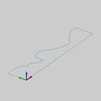
Leave the file in the ISO 2 view. -
In the Surfaces group, of the Create 3D ribbon, click
Revolve Surface.
The Revolve Surface parameters display in the Data Entry Manager. -
Deselect the Previewcheck box.
Note: This stepis not necessary to the creation of a Revolve and is used in this exampleonly to allow us to see the result of the chain selection easier.
-
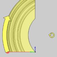
In the graphics area, hover over the entity shown below, andpress and hold Shift, beforeclicking the entity to chain-select the entire chain.
Tip: Noticethat the direction arrow is now displayed on the geometry.When you chainselect an entity for functions that have a direction, the nearest snappoint of the entity that you select is defined as the end of the chain.Alternatively, you can click an entity to define the start of the chain,and then hold Shift and click the end of another entity to define theend of the chain.The steps in this example eliminate the extra selection.When you are selecting a closed chain to revolve, the start and end locationof the chain are not important.
-
Select the Preview checkbox.
The Preview displays.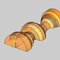
-
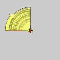
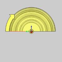
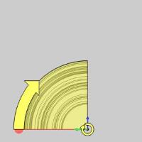
In the Rotation Anglebox, enter a value of 90.00 andpress Tab.
The Preview Updates.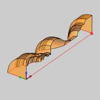
-
Select the With Caps checkbox.
The Preview updates to show the Revolve Surface being created as solidinstead of a single revolved surface.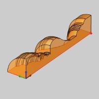
-
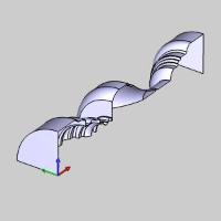
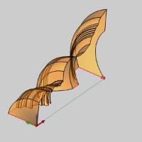
To create the geometry as shown in the CAD preview, in the DataEntry Manager, click OK.The profileis revolved 90 degrees around the X-axis and a
Revolve feature is createdin the CADTree.
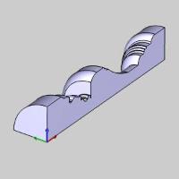
-
To end the function, click Cancel.
This concludes Example 1.Leave the file open and continue to Example2 to learn more about Revolve Surface.
Example 2 (Pick the Revolve Axis)
-
After completing Example 1, press Ctrl+Zto undo the last revolve.Or, in the quick access toolbar, click
 .
. -
In the Move group of the Utilities ribbon,click
 Rotate.
The Rotate parameters display in the Data Entry Manager. -
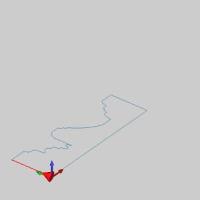
Hover over the an entity in the chain, thenhold Shift and click thatentity to chain select the entire chain.


The entities are added to the Selected Geometry list. -
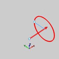
For the Angle Around Axis group, enter:
- X 10.0000
- Y 10.0000
- Z 10.0000
For the Origin group, enter:
- X 1.0000
- Y 1.0000
- Z 1.0000
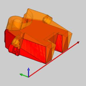
The Preview updates for each entry.Withthe values entered, the preview should match the one seen in the imagebelow.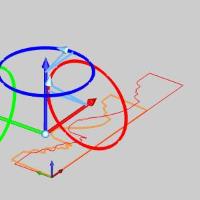
-
Click OK to finalizethe rotation.
The Preview updates to show the results should the current values beapplied again.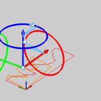
-
In the Surfaces group, of the Create 3D ribbon, click
Revolve Surface.
The Revolve Surface parameters display in the Data Entry Manager. -
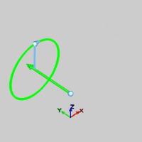
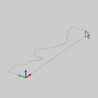
Click the entity shown in the image below to set the start pointand direction of the Revolve Curve.
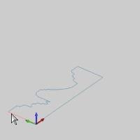
The Start arrow appears. -
Hold Shift and click the entity shown in the image below toset the end point of the Revolve Curve.
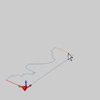
The Preview appears.
Notice it is not the result obtained from Example 1.Since we haverotated the wireframe, it's intended rotation axis is no longer parallelto the X Axis. -
In the Rotation Axis group, click PickAxis.This will allow us to select the rotation axis for thefunction from geometry in the graphics area.
The preview disappears.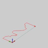
-
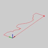
Click in the Rotation Axis list to give it focus.
The Rotation Axis list highlights to allow us to select the RotationAxis. -
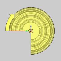
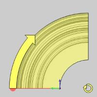
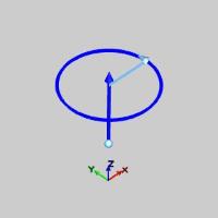
Click the entity shown in the image below.
Once selected, the Preview displays.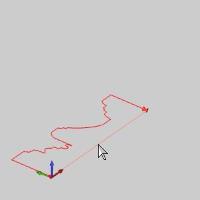
-
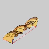
Click OK to finalizethe Revolve.
The surface is created in the graphics area and aRevolvefeature is created in theCAD Tree.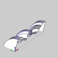
Note: Notice,even though we have With Capsselected, we have not created a solid.To create a solid that does notrevolve a full 360 °, a closed chain needs to be selected as the RevolveCurve.
-
To end the function, click Cancel.
This concludes the examples.