


 Sweep Surface
Introduction
This topic will explain the Sweep Surface function, and the optionsfound in it.This topic will also describe where to find the function,provide quick steps and an example on how to use it, and provide links to related topics.
The Sweep Surface Function
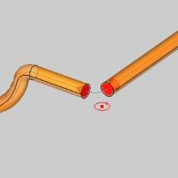
The Sweep function is used to create a surface by sweeping a wireframechain (profile curve) along another wireframe chain (sweep path).Notethat the profile curve does not require any special orientation or locationas it is automatically moved to the sweep path based on the selected attachmentpoint and chain direction.
Tip: Ingeneral, the sweep path should be smooth, meaning it doesn't containany sharp corners, which may cause unexpected results.(If the sweep functionfails due to a sharp corner, the software automatically recreates thesweep path so the function doesn't fail.) Adding a small radius to sharpcorners can help you obtain the expected result.
Navigation
To open Sweep Surface:
-
In the Surfacesgroup, of the Create 3D tab, click
 Sweep Surface.
The parameters display in the Data Entry Manager.
The Data Entry Parameters
-
 Preview - Select the check box to enable the CAD preview, which displays what the result will be before you create it. Once all geometry is selected, the preview is shown.
  Preview - Clear the check box
to turn off the CAD preview.
Preview - Clear the check box
to turn off the CAD preview.
Attachment Point
|
|
|
| The list box will list the entity currently selected for the function. | |
Sweep Profile
|
|
|
| This list box will show the entity currently selected for the function. | |
Sweep Path
|
|
|
| This list box will show the entity currently selected for the function. | |
- OK - finalizes the function.
- Cancel - exits the function.
Quick Steps - Sweep Surface
-
Open the function.
The Sweep Surface parameters display in the Data Entry Manager and the Attachment Point list is given focus to acceptselection of a point or snap point. -
Select a point.
This determines where the Sweep Profile is attached to the Sweep Path.
The point is added to the Attachment Point list and the focus is movedto the Sweep Profile list.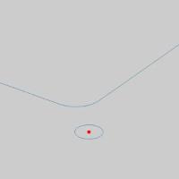
-
Hold Shiftand click the arc.
The chain is added to the Sweep Profile list and the focus is movedto the Sweep Path list. -
Click near the end of the first chain entityto set the start of the chain.
Hold Shiftand click near the end of the last entity to set the end of the chain.
Tip: When usinga closed chain, where all entities are to be included in the Sweep Path,you can hold Shift and click nearthe end of the last entity to set the start and end of the chain in oneclick.
The chain is added to the Sweep Path list.
If the ![]() Preview option is selected The CAD preview isautomatically created once the Attachment Point, Sweep Profile, and SweepPath each have geometry in their lists.
Preview option is selected The CAD preview isautomatically created once the Attachment Point, Sweep Profile, and SweepPath each have geometry in their lists.
-
To create the surface as shown in the preview, click OK.
The feature is added to the CAD Tree.
You can repeat this process for any other surfaces. -
To close the function, click Cancel.
Example
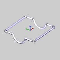
Note: In theimages below, the Show Axis X-Ytoggle has been disabled in the AxisX-Y group of the Settings Part> Display dialog.The Gnomon has been used to show the SweepProfile in the X,Y Plane.
-
In the Quick Access Toolbar, click
 Open.
Open. -
In the Opendialog box, navigate to C:\BobCAD-CAMData\BobCAD-CAM V**\Examples.
Note: This isthe default install location.If you performed a custom install, navigateto the location in which you installed the software.
-
Select Sweep_Surface_Example.bbcd,and click Open.
The file opens.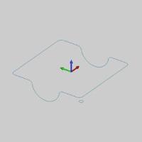
Leave the file in the ISO 2 view. -
In the Surfacesgroup, of the Create 3D tab, click
Sweep Surface.
The Sweep Surface parameters display in the Data Entry Manager and the Attachment Point list is given focus to acceptselection of a point or snap point. -
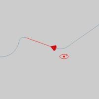
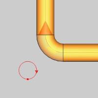
The first step is to select a point or snap point to assignas the Attachment Point of the Sweep Profile to the Sweep Path.
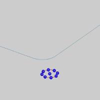
Hover overthe small arc to display the snap points of the arc.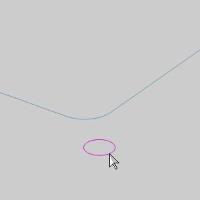
-
Click the snap point in the center of the arc to select it.

The point is added to the Attachment Pointlist and the focus is moved to the Sweep Profile list.
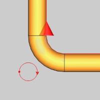
-
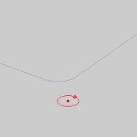
The next step is to select the Sweep Profile itself.
Press and hold Shift,and click the arc to select it define he profile geometry that is sweptalong the Sweep Path.

The chain is added to the Sweep Profile listand the focus is moved to the Sweep Path list.
Note: Becauseour Sweep Profile is a single entity, we used chain selection to definethe start and end of the profile in one click.If you were using a groupof connected entities as the sweep profile, you can still use this method,or you can click the start entity first, and then hold shift and clickthe last entity to define the end of the sweep profile.This methodis helpful when you have a group of connected entities, but you don'twant to select them all.An example of this selection method is performedin the next step.
-
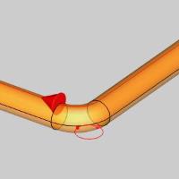
The next step is to select geometry as the Sweep Path.Becausewe are selecting a closed sweep path, we could just hold Shift andclick anywhere along the path to select it and define the directionin one click.Instead, we use the two click method and skip an entityto show how it is done.
Click the end of entity shown below to set the start of the sweep path.
The start arrow of the sweep path displays.
-
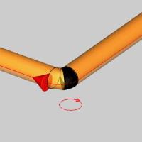
To set the end of the sweep path, hold Shiftand click near the end of the entity shown below.
The Preview displays.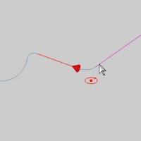
Note: Even thoughthe chain for the sweep path is a closed path, we have selected the chainin such a way that we have avoided including a particular entity.Hadwe held Shift when clicking the first entity of the sweep path, all entitieswould have been included.
-
Next to the Sweep Path list, click
 (Delete)to remove the partial chain from the list.
The Preview disappears. -
Hold Shift and selectan entity of the sweep path as shown below.
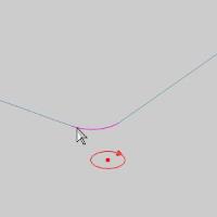
The Preview updates.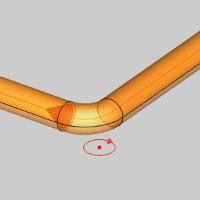
-
To finalize this result, we would click OK.Before we do that,we will test different Attachment Points by repeating the followingthree steps:
-
Click
(Delete) next to the Attachment Point list to remove the existingpoint.
The Preview and the Attachment Point disappears.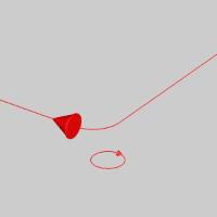
-
Click in the Attachment Point list to give it focus.
-
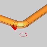
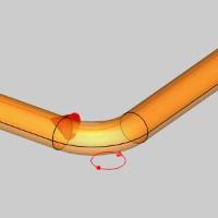
With the available snap points of an arc in mind, clickone to test a new AttachmentPoint.
Repeat sub-steps 1,2, and 3 to get the followingresults.
|
ISO 2 View |
ISO 2 View |
ISO 2 View |
ISO 2 View |
|
|
|
|
|
|
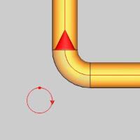
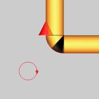
Top View |
Top View |
Top View |
Top View |
|
|
|
|
|
-
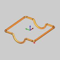
Click OK to finalizethe previewed result.
The surface is created in the graphics area and aSweepfeature is created in the  CAD Tree.
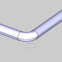
Note: The Resultshown in the image above uses the center of the arc as the AttachmentPoint.
-
Click Cancel to exitthe function.
This concludes the example.