


 Break Angle
Introduction
This topic will explain the Break Angle function, describe where to find it, and the optionsfound in it.This topic will also provide quick steps and an example on how to use it, and provide links to related topics.
The Break Angle Function
The Break Angle function breaks arcs at the defined angle of rotationfrom the zero degree position (the 3 o'clock position).
Navigation
To open Break Angle:
- In the Break group, of the Utilities ribbon, click
 Break Angle.
The Parameters open in the Data Entry Manager.
The Data Entry Parameters
 Break Option
![]()
![]()
![]()
![]()
![]()
Entity Selection
- Break At Angle - sets the angle value along an arc at which the arc is split.The arc must pass through this value in order for it to be broken, or the function will fail.The angle value is always from the zero degree position (3 o'clock) of the XY plane of the arc.
-
OK - has no use with this function.
- Cancel - cancels the functionwhen finished.
Quick Steps - Break Angle
- Open the function.
- Set the Break At Angle to the desired angle.
Note: The Break Angle function only applies to arcs, and the Break At Angle amount is always an absolute amount with 0° and 360° both occupying the 3 o'clock position.
- Hover over the arc to be broken.
A preview appears showing the point at which the break will occur.
Click the entity.
The entity is broken. - Repeat as necessary.
- Click Cancel to exit the function.
Example
The Break Angle function is used to break arc entities at a definedangle interval along the arc.
The following image shows the angles and the positive direction of rotationused when creating arcs.
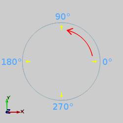
As you can see in the previous image, the zero degree reference isthe X-axis of the active drawing plane.The angle values shown arefollowed when using the Break Angle function.
-
In the Quick Access Toolbar, click
 New.
New. -
In the Entity group, of the Create 2D ribbon, click the down arrow under
 Arc, and select
  Arc Center.
 -
In the Data Entry Manager, click OK to create the default arc asshown in the CAD preview.
- In the Break group, of the Utilities ribbon, click Break Angle.
-
In the Anglebox, type 120.00.
Note: Right-clickanywhere in the graphics area, and click EntitySummary.At the top of the dialog box, notice the Quantity of Entitiesbox displays 1.To close the dialog box, click OK.
-
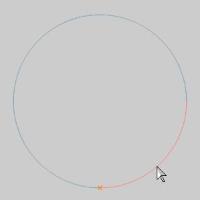
In the graphics area, point to thearc so that it displays in the Highlight color.
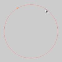
The break point preview displays.
Notice that the entire arc is highlighted.This shows that the arc is a single entity.
-
Click to select the arc.Notice thatit no longer displays in the Highlight color.

To visually confirm the change, point tothe upper right-hand side of the arc.
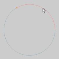
Notice that the arc is broken at 120 degrees.The original arc is now two separate arc entities.
-
Right-click anywhere in the graphicsarea, and click Entity Summary.
Notice that the Quantity of Entities boxnow displays 2.
When using Break Angle, the arc doesn't haveto be a full circle.As long as you use proper values, you can still breakpartial arcs within the proper angle range.The following steps illustratethis point.
-
In the Data Entry Manager, change theAngle value to 270.00.
-
In the graphics area, click toselect the arc in Quadrant 1.
Notice that an error message is displayed: No intersection point at this angle (arc may already be broken here).
-
To close the error message, clickOK.
-
This time, click to select the otherarc.
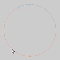
The arc is broken at 270 degrees.Noticethat we broke an arc that started at 120 degrees.This shows that theangle value is not in reference to the start of the arc itself, but ratherthe X-axis (zero degree location).
When you point to the arc now at differentlocations, you can see that there are three arc entities.You can usethe Entity Summary to confirm.
-
To end the function, in the Data Entry Manager, click Cancel.
This concludes the example.