


Assigning Lathe Tool Holders
Introduction
Bob
To Assign a Custom Tool Holder
-
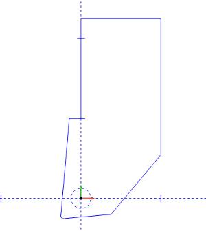
In the graphics area, draw the 2D shape of the holder.
At the position of the attachment point of
the tool insert, place a
It does not matter which dashed pattern is chosen, just that the circle itself is not solid.
-
To open the Tool Library, do one of the following:
-
-
Right-click
 CAM Defaults, and click
Tool Library.
CAM Defaults, and click
Tool Library.
-
-
-
Right-click
 Turning
Tools, and click Tools.
Turning
Tools, and click Tools.
-
-
In the Tool Library, select the lathe tool category that you want to modify.
-
In the list on the right side of the dialog box, click the tool that you want to modify, expand the Tool Parameters on the right side of the dialog.
(If you are creating a new tool, just select the category, and click Add.) -
In the Tool Parameters section, click Edit Tool Holder.
-
In the Tool Holder Definition dialog box, select the radio button for Custom.
-
Click Pick Geometry.
The Tool Holder Definition dialog box hides and the
-
In the graphics area, click and drag a window around the entire drawing to select the holder geometry.
The holder geometry is added to the Holder Shape list, while the dashed/dotted Match Circle is automatically added to the Match Circle list. -
Click OK to confirm the geometry selection and exit the Tool Shape Picking list.
The holder geometry is now assigned to the selected tool. -
Click OK to save the changes and return to the Tool Library.