


Assigning Lathe Tool Inserts
Introduction
Bob
To Assign a Tool Insert
- In the graphics area, draw the 2D shape of
the insert.
- At the position of the attachment point to
the tool holder, place a
It does not matter which dashed pattern is chosen, just that the circle itself is not solid. - Place a point at the theoretical tool point.
This point is normally tangent to the forward and bottom extents of the tool nose radius.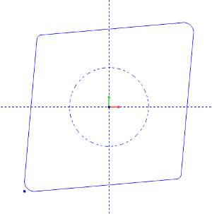
- To open the
Tool Library, do one of the
following:
- Right-click
 CAM Defaults,
and click Tool Library:
CAM Defaults,
and click Tool Library: - Right-click
 Turning
Tools, and click Tools,
Turning
Tools, and click Tools, - In the Tool Library, select the lathe tool
category that you want to modify.
- In the list, click the tool that you want
to modify, and click expand the Tool Parameters section on the right.
(If you are creating a new tool, just select the category, and click Add.) - In the Create/Modify dialog box, select
the radio button for Custom Shape.
- Click Assign Tool Insert.
- In the graphics area, to select the insert
geometry, click and drag a window around the entire drawing.
The Insert Shape, Match Circle, and Reference Point are all automatically assigned to the proper lists. - Click
 OK.
OK.
The holder geometry is now assigned to the selected tool.
Click OK to save the changes and return to the Tool Library.
Note: The Tool Attachment Circle is only required if the insert is to be associated with a tool holder.