Geometry Selection: CAM Features
Introduction
This topic will explain geometry selection for CAM features, will explain different methods available, and will provide links to related topics.
CAM Geometry
For every CAM feature created in BobCAD-CAM you must select the geometry to be associated with it. There are various methods that can be used when selecting the geometry, and being aware of the available selection methods can help you to become more efficient when selecting geometry.
Selection Methods
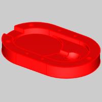
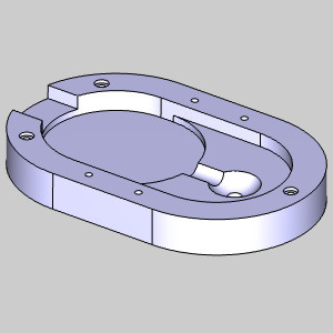
There are many ways to select geometry for CAM features. You can select wireframe geometry, solid edges, or surfaces. Some example images are shown next for different types of features.
Mill Example
Mill Drill/Tap Hole
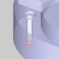
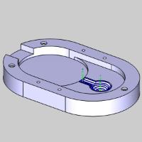
When working with holes, you can select points, wireframe geometry, surface edges, or the cylindrical surface of the hole itself.
- Points
When selecting points, you can select points from the top of the hole, from the bottom of the hole, or at any point along the Z Axis of the hole.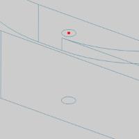
If you select a point at the top or bottom, you can choose the Use As Top, or Use As Bottom options in the Hole Geometry picking dialog. This will allow you to have the Top of Feature, or Feature Depth values set in the Mill Hole Wizard automatically, leaving you to enter the other manually. The problem with using points, is that you will need to set the Diameter of the hole manually. - Wireframe
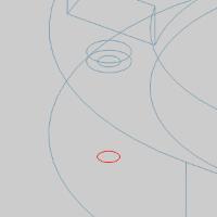
When selecting wireframe, you can select arcs from the top of the hole, from the bottom of the hole, or at any point along the Z Axis of the hole as well as lines running through the center of the intended drill position.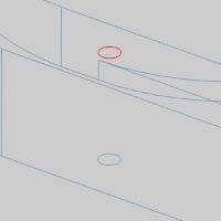
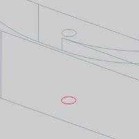
If you select an arc from the top or bottom, you can choose the Use As Top, or Use As Bottom options in the Hole Geometry picking dialog. This will allow you to have the Top of Feature, or Feature Depth values set in the Mill Hole Wizard automatically, leaving you to enter the other manually. - Edges
When selecting edges, you can select the surface edge from the top of the hole, or from the bottom of the hole.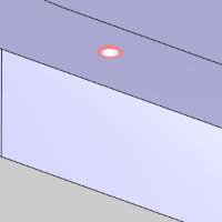
When you select the surface edge from the top or bottom, you can choose the Use As Top, or Use As Bottom options in the Hole Geometry picking dialog. This will allow you to have the Top of Feature, or Feature Depth values set in the Mill Hole Wizard automatically, leaving you to enter the other manually. - Surfaces
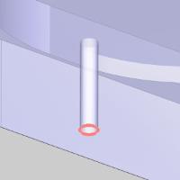
When selecting cylindrical surface of the hole itself, the Top of Feature and Feature Depth values will be set for you automatically.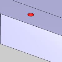
If a surface is available for selection, this is the recommended method.
Mill Counterbore/Counterbore Tap Hole
When working with counterbore holes, you can select points, wireframe geometry, surface edges, or the cylindrical surface of the hole itself. When selecting the geometry, pick the geometry for either the counterbore, or the hole, and not both. Selecting geometry to represent both the hole and the counterbore, will result in two separate features being created. In general it is recommended that geometry for the hole diameter be selected.
- Points
When selecting points, you can select points from the top of the hole, from the bottom of the hole, or at any point along the Z Axis of the hole.

If you select a point at the top or bottom, you can choose the Use As Top, or Use As Bottom options in the Hole Geometry picking dialog. This will allow you to have the Top of Feature, or Feature Depth values set in the Mill Hole Wizard automatically, leaving you to enter the other manually. The problem with using points, is that you will need to set the Diameter of the hole manually. The counterbore diameter and depth will need to be set manually as well. - Wireframe
When selecting wireframe, you can select arcs from the top of the hole, from the bottom of the hole, or at any point along the Z Axis of the hole as well as lines running through the center of the intended drill position.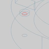
If you select an arc from the top or bottom, you can choose the Use As Top, or Use As Bottom options in the Hole Geometry picking dialog. This will allow you to have the Top of Feature, or Feature Depth values set in the Mill Hole Wizard automatically, leaving you to enter the other manually. The counterbore diameter and depth will need to be set manually as well. - Edges
When selecting edges, you can select the surface edge from the top of the hole, or from the bottom of the hole.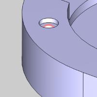
When you select the surface edge from the top or bottom, you can choose the Use As Top, or Use As Bottom options in the Hole Geometry picking dialog. This will allow you to have the Top of Feature, or Feature Depth values set in the Mill Hole Wizard automatically, leaving you to enter the other manually. The counterbore diameter and depth will need to be set manually as well. - Surfaces
When selecting cylindrical surface of the hole itself, the Top of Feature and Feature Depth values will be set for you automatically. Only the counterbore diameter and depth will need to be set manually.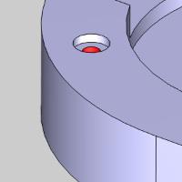
If a surface is available for selection, this is the recommended method.
Mill 2 Axis
When working with 2 Axis features, you can only select points/snap points when selecting Top of Feature and Total Depth. For the feature geometry you can select wireframe geometry, surface edges, or surface faces. In most cases, selecting surface edges, or faces works well. When selecting geometry, remember that the Top of Feature and Total Depth do not rely on the feature geometry. Because of this, the selected geometry can be located anywhere along the Z Axis of the intended feature.
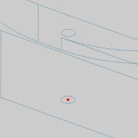
- Points
The only time points are utilized in Mill 2 Axis features are when setting the Top of Feature and Total Depth.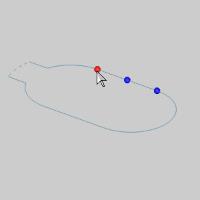
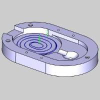
- Wireframe
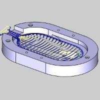
In some cases selecting wireframe is necessary. Some part features may warrant a pocket feature even though the geometry itself is not actually a closed pocket. In this case, you would need to pull wireframe geometry to adjust to suit your needs. In the case of open pockets for the Advanced Pocket patterns, like the one in the images below, you must have a dotted line representing the open end. This too necessitates wireframe geometry.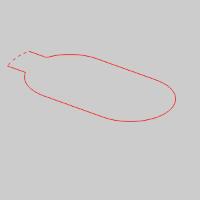
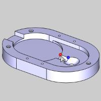
- Edges
When selecting edges,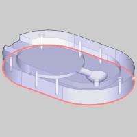
- Surfaces
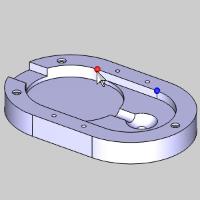
When selecting surfaces, keep in mind that all edges of the selected surfaces will be used to create the geometry for the feature. In the images shown below, the surface has no additional features that would cause an issue. If this surface had a hole in the center that we wanted to machine over with a pocket operation, we would not be able to select the surface, and would instead need to selected the outer edges only.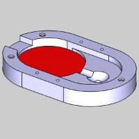
Mill 3 Axis
When working with 3 Axis features, you can select surfaces, or the entire solid for the geometry itself, and wireframe or surface edges when assigning boundaries.
- Points
The only time points are utilized in Mill 3 Axis features are when setting the Top of Job and Bottom of Job. Actual points are not even needed for this. In the images below, you will notice the Top of Job being set with
- Wireframe (for Boundaries)
In some cases selecting wireframe for your boundaries are necessary. While the toolpaths that become available with the Mill 3 Axis Pro package offer boundary offsets directly in the operations, without those toolpaths, you must create your own boundary offsets when necessary. This is where wireframe boundaries become important.
- Edges (for Boundaries)
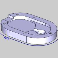
When selecting edges, you can select them individually, or right-click the edge and select the Constant Z, or Loop Selection, options to pick an entire chain at once. To select the edges seen in the images below, picking each individually was the easiest method since the Constant Z and Loop Selection options selected many unwanted edges. For more information on the Constant Z and Loop Selection methods, see the How to Use Loop Selection topic.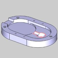
- Surfaces
When selecting surfaces, keep in mind that all surfaces not selected for the feature are not 'seen' by the feature. This means toolpath could be gouging other surfaces. Selecting the individual surfaces wanted for a feature is not recommended.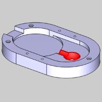
- Solids
When selecting surfaces, keep in mind that all edges of the selected surfaces will be used to create the geometry for the feature. In the images shown below, the surface has no additional features that would cause an issue. If this surface had a hole in the center that we wanted to machine over with a pocket operation, we would not be able to select the surface, and would instead need to selected the outer edges only.