


The UCS
Introduction
This topic will introduce the idea of the UCS and define the difference between the UCS, and the WCS. This topic will also show how to set a UCS as the active UCS, and show how to create a new UCS.
UCS vs WCS
The WCS, or World Coordinate System, is the underlying coordinate system everything in the system is based on and it shares is location and orientation with the Top(X/Y) Plane, and is always visible in the lower left of the graphics area, as seen in the image below. Other Coordinate systems can be created on top of the WCS however, and these are referred to as User Coordinate Systems. A UCS, or User Coordinate System, is a coordinate system whose X, Y, Z zero positions have been redefined for the purposes of making the current drawing, or at least the current portion of the design, easier to draw for the user. Not only can the location of the X, Y, Z zeros be redefined, the vector direction, or orientation, of the UCS itself can also be redefined.
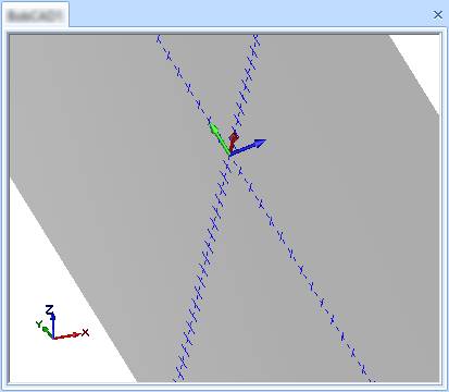
| In the above image: | ||

|
The WCS - | This will always show the orientation of the WCS and cannot be hidden. |

|
The UCS Plane - | This shows the position and orientation of the current UCS. The color and level of transparency can be adjusted in Settings Part and Settings Default. |

|
The Axis X-Y - | This shows the position and orientation of X, and Y axis of the current UCS, as well as the unit Tick Marks. The color and number of Tick Marks can be adjusted in Settings Part and Settings Default, and its visibility can be toggled in the same screens. |

|
The Gnomon - | This shows the position and orientation of X, Y, and Z axis of the current UCS. Its visibility can be toggled in Settings Part and Settings Default screens. |
The UCS Manager
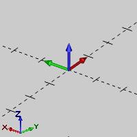
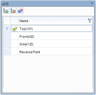
The UCS Manager is used to select between existing user coordinate systems, to modify existing user coordinate systems, and to create new user coordinate systems. The default user coordinate systems are, Top (X/Y), Front (X/Z), and Side (Y/Z). The default coordinate systems cannot be modified, but others can be created, and at any point in the drawing process, you can click on a particular UCS in the UCS Manager to make that the active coordinate system. When you set a UCS as active, the coordinate system in the graphics area is updated to reflect the selected UCS. CAD geometry is always created using the X,Y, and Z zeros of the Active UCS.
|
Top UCS |
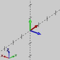
Front UCS |
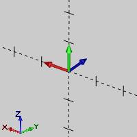
Side UCS |
|
|
|
|
Navigation
The default location of the UCS Manager is the right-hand side of the user interface. When the pane is docked with other Managers, as is the case by default, clicking the UCS tab will access the UCS Manager.
The Shortcut and Quick access menus
You right-click anywhere in the UCS window, or the UCS name, to access a shortcut menu with the following commands. The Add New UCS, Modify UCS, and Delete UCS options are also available as buttons in the quick access menu at the top of the UCS Manager.
 Active UCS
- sets the selected UCS as the active UCS.
Active UCS
- sets the selected UCS as the active UCS. Add New
UCS - adds a new UCS to the list and opens the Create
UCS dialog box in the Data Entry Manager for you to
define the new UCS.
Add New
UCS - adds a new UCS to the list and opens the Create
UCS dialog box in the Data Entry Manager for you to
define the new UCS.  Modify UCS
- opens the Modify UCS dialog box in the Data Entry Manager for you to change the location of the selected UCS.
Modify UCS
- opens the Modify UCS dialog box in the Data Entry Manager for you to change the location of the selected UCS. Delete UCS
- removes the selected UCS from the list. You can't delete the default
(Top, Front, or Side) work planes.
Delete UCS
- removes the selected UCS from the list. You can't delete the default
(Top, Front, or Side) work planes.
The Create UCS / Modify UCS Dialog Box Parameters
When you click Add New UCS, or Modify UCS, the following parameters display in the Data Entry Manager.
Create UCS / Modify UCS
Create UCS, and Modify UCS are the main groups that encompasses all
of the functionality available to create, or modify a UCS.
- UCS Name - allows you to
enter the name for the UCS being created, which will appear in the
UCS Manager when you click OK
to confirm creation.
Creation Options
The Creation Options group will allow you select the method used to create the UCS.
 Snap
- uses a snap point, that you select in the graphics area, to set
the origin (X0,Y0,Z0) of the UCS. Each selection will be added to
the Selected Geometry list, with only the last point in the list being
utilized.
Snap
- uses a snap point, that you select in the graphics area, to set
the origin (X0,Y0,Z0) of the UCS. Each selection will be added to
the Selected Geometry list, with only the last point in the list being
utilized.
 3-Points
- uses three points, that you select in the graphics area, to create
the UCS. Each selection will be added to the Selected Geometry list,
with only the last three points in the list being utilized.
3-Points
- uses three points, that you select in the graphics area, to create
the UCS. Each selection will be added to the Selected Geometry list,
with only the last three points in the list being utilized. - Translate
- creates a new UCS based on the currently active UCS, and enables
the X, Y,
and Z boxes in the Translate
group for you to type incremental translation values, by which the
new UCS will be shifted.
- Planar Face
- enables the selection of a planar face to define the UCS location.
Each selection will be added to the Selected Geometry list, with only
the last point in the list being utilized.
- Cylindrical
Face - enables the selection of a cylindrical face to define
the UCS location. Each selection will be added to the Selected Geometry
list, with only the last point in the list being utilized.
- Rotate - creates a new UCS based on the currently
active UCS, and enables the X,
Y, and Z
boxes in the Rotation Angle group for you to type angle values,
by which the new UCS will be rotated.
Selected Geometry
The Selected Geometry list becomes available when the Snap, 3-Points, Planar Face, or the Cylindrical Face Creation Options are selected. The Selected Geometry list will show all geometry selected for the UCS creation, but will only utilize the last relevant geometry. As an example, although the selected geometry list may show many geometries, the Snap option will only use the last geometry, and the 3-points option will only use the last three points.
-
 Delete
- When a particular geometry in the list has been highlighted,
Delete will remove the selected geometry from the list.
Delete
- When a particular geometry in the list has been highlighted,
Delete will remove the selected geometry from the list. -
 Delete
All - will remove all geometry from the list.
Delete
All - will remove all geometry from the list.
Translate
The Translate options becomes available when Translate method is selected from the Creation Options. The Translate options will present you with X,Y, and Z inputs to allow you to shift the UCS being created.
- X- determines the change in distance
along the X-axis from the current UCS.
- Y- determines the change in distance
along the Y-axis from the current UCS.
- Z- determines the change in distance along the Z-axis from the current UCS.
Rotation Angle
The Rotation Angle options becomes available when Rotate method is selected from the Creation Options. The Rotate options will present you with X,Y, and Z axis inputs around which the UCS being created can be rotated around.
- X- determines the amount of rotation
around the X-axis of the current UCS.
- Y- determines the amount of rotation
around the X-axis of the current UCS.
- Z- determines the amount of rotation around the X-axis of the current UCS.
 UCS Coordinate System
The UCS Coordinate System section contains the Coordinate System group which will give you the control to modify the current location and orientation of the UCS being created. The chevron to the left will also allow you to collapse and expand the entire section.
- Allow Modification
 - With this
option deselected, no further modification of the position or orientation
of the UCS is available.
- With this
option deselected, no further modification of the position or orientation
of the UCS is available.  - With this
option selected, the Coordinate System group is enabled, allowing for
position and orientation alterations to the UCS being created.
- With this
option selected, the Coordinate System group is enabled, allowing for
position and orientation alterations to the UCS being created.
Coordinate System
The Coordinate System group will allow you to adjust the origin location, and the vector direction of the axis, by selecting geometry from the graphics area, or entering values manually. When selecting geometry from the graphics area to associate with an axis direction:
- Points:
points the axis toward the point.
- Lines:
points the axis along their vector direction.
- Arcs:
a line is formed from the start to the end angle of the arc, and the vector
of that line is used.
- Circles:
the normal of the circle is used.
- Splines:
a line is formed from the start to the end of the spline, and the vector
of that line is used.
- Surfaces:
uses the normal of the surface.
- Cylinders: uses the cylindrical axis.
Note: Keep in mind, when defining the vector of a particular axis manually, the other axes must update to maintain a perpendicular relationship with each other. The X,Y, and Z values of the vectors are separated with a semicolon.
- Origin
- is used to select geometry in the graphics area to set as the origin
for the UCS.
-
(Delete) - will remove the selected
geometry from the list.
- X - determines the change in
distance along the X-axis from the current UCS.
- Y - determines the change in
distance along the Y-axis from the current UCS.
- Z - determines the change in distance along the Z-axis from the current UCS.
- X
Direction - is used to select geometry in the graphics area
to align the X axis of the UCS to.
-
 (Reverse) - will reverse the direction
of the associated UCS axis.
(Reverse) - will reverse the direction
of the associated UCS axis.
- X - determines the vector of
the X axis in the UCS being created.
- Y - determines the vector of
the Y axis in the UCS being created.
- Z - determines the vector of the Z axis in the UCS being created.
- Y
Direction - is used to select geometry in the graphics area
to align the Y axis of the UCS to.
-
(Reverse) - will reverse the direction
of the associated UCS axis.
- X - determines the vector of
the X axis in the UCS being created.
- Y - determines the vector of
the Y axis in the UCS being created.
- Z - determines the vector of
the Z axis in the UCS being created.
- Z
Direction - is used to select geometry in the graphics area
to align the Z axis of the UCS to.
-
(Reverse) - will reverse the direction
of the associated UCS axis.
- X - determines the vector of
the X axis in the UCS being created.
- Y - determines the vector of
the Y axis in the UCS being created.
- Z - determines the vector of the Z axis in the UCS being created.
- OK - performs the
function
- Cancel - cancels the function when finished.
Setting the Active UCS
The UCS that is selected prior to using a CAD function determines the
drawing plane. To set the Active UCS, simply click on the row of the layer.
When you set the active UCS, the ![]() UCS
icon is placed in the row of the active UCS.
UCS
icon is placed in the row of the active UCS.
Quick Steps - How to Create User Coordinate Systems
- In the UCS Manager, right-click anywhere and select Add New UCS, or just click the icon in the quick access menu.
The Create UCS dialog opens in the Data Entry Manager. - Set the name for the new UCS by typing it in the UCS Name text field.
- In the Creation Option group, select one of the following:
Snap
This method of creating a new user coordinate system allows you to specify the new origin using snap locations. The following is a step-by-step procedure:
- With Snap Point selected, the Selected Geometry list box has focus which allows you to select a point or snap point.
Select a point or snap point.
The point is added to the Selected Geometry list and a preview of the UCS placement appears in the graphics area. - Select the Modify check box and use the Coordinate System group to alter the previewed placement if necessary.
- Click OK.
The new user coordinate system is created and set to the active UCS.
By 3 Points
The 3-Point method of creating a new UCS allows you to create a UCS using 3 existing snap points in the graphics area. The first selected point indicates the origin, or X0, Y0, Z0 of the new UCS. The second selected point establishes the X positive direction and the third selection indicates the Y positive direction.
- With 3-Points selected, the Selected Geometry list box has focus which allows you to being selecting points or snap points.
Select a point or snap point.
The point is added to the Selected Geometry list, and the Origin is established. - Select a point in order to orient the X positive direction.
The point is added to the Selected Geometry list, and the X positive direction is established. - Select a point in order to orient the Y positive direction.
The point is added to the Selected Geometry list, the Y positive direction is established, and a preview of the UCS placement appears in the graphics area. - Select the Modify check box and use the Coordinate System group to alter the previewed placement if necessary.
- Click OK.
The new user coordinate system is created and set to the active UCS.
Translate
The Translate method of creating a new UCS allows you to specify a location in X, Y and Z for the position of a new user coordinate system. The values used to translate the UCS are based on the current active UCS.
- With Translate selected, a preview of the UCS placement appears in the graphics area, and the Translate group becomes available.
Specify the X, Y, and Z values.
The preview of the UCS placement updates in the graphics area as the values are updated. - Select the Modify check box and use the Coordinate System group to alter the previewed placement if necessary.
- Click OK.
The new user coordinate system is created and set to the active UCS.
Planar Face
The Planar Face method of creating a new UCS allows you to select a Planar Face in order to set the location and orientation of a new user coordinate system.
- With Planar Face selected, the Selected Geometry list box has focus which allows you to select a planar surface.
Select a planar surface.
The face is added to the Selected Geometry list and a preview of the UCS placement appears in the graphics area. - Select the Modify check box and use the Coordinate System group to alter the previewed placement if necessary.
- Click OK.
The new user coordinate system is created and set to the active UCS.
Cylindrical Face
The Cylindrical Face method of creating a new UCS allows you to select a Cylindrical Face in order to set the location and orientation of a new user coordinate system.
- With Cylindrical Face selected, the Selected Geometry list box has focus which allows you to select a cylindrical surface.
Select a cylindrical surface.
The face is added to the Selected Geometry list and a preview of the UCS placement appears in the graphics area. - Select the Modify check box and use the Coordinate System group to alter the previewed placement if necessary.
- Click OK.
The new user coordinate system is created and set to the active UCS.
Rotate
This method of creating a new UCS allows you to rotate the X/Y plane a specific angle around the global X0, Y0, Z0. The following is a step-by-step procedure:
- With Rotate selected, a preview of the UCS placement appears in the graphics area, and the Rotate Angle group becomes available.
Specify the X, Y, and Z rotation angle values.
The preview of the UCS placement updates in the graphics area as the values are updated. - Select the Modify check box and use the Coordinate System group to alter the previewed placement if necessary.
- Click OK.
The new user coordinate system is created and set to the active UCS.