


How to Vectorize Using the Multi-Color Strategy
Introduction
This topic explains how to vectorize an image using BobART.The useof the Multi-Color Strategy is the main focus, but the Black and Whitestrategy is also examined.Many useful tips and a few different approachesare provided.
Example File
If you are connected to the Internet, the part file for this example can be downloaded automatically by clicking the following link: Multi-Color Vectorization Example 1.bbcd
Once you download and saved the zip file, extract the files on your system in an easy place to remember.You can then open the file to use with this tutorial.All files for the tutorials in this help system available for download can be found by clicking on the following link: http://www.bobcad.com/helpfiles.
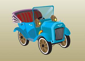
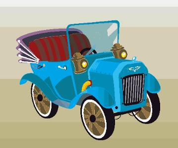
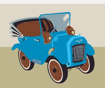
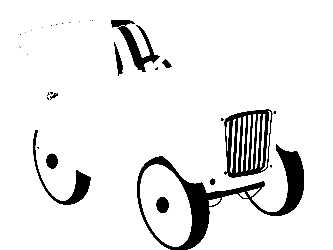
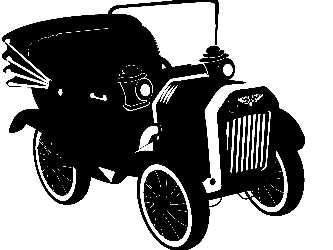
In this example, a color image of a car is used to create vector geometry.The image used is shown next.
This tutorials explains the following BobARTfunctionality:
-
Loading an image using the BobARTManager
-
Selecting the image location
-
Hiding and showing images
-
Moving and scaling images
-
Using the Vectorize... dialogto vectorize an image
-
The 2-level black and white strategy
-
The multi-color strategy
-
-
Using Remove Chains Less Than
-
Editing the vectorization parameters
-
Exploring workflow methods and manyhelpful tips
Part 1) Open the Example File
-
Click File > Open.
The Open dialog is displayed. -
In the Opendialog, select the folder in which you saved the example files.
-
Select Multi-ColorVectorization Example 1.
The file is opened (the graphics area is empty). -
Click the
 BobART tab to access the BobArt Tree.
Part 2) Load the Image, Select Location, Size and Transparency
Note: For this example, we are simply vectorizing an image without using othergeometry, so we can focus on the process of vectorizing the image.Youmay want to move or scale an image in order to use the resulting geometrywith an existing model.This section shows you how to do so.You can usethese steps before or after vectorizing an image, depending on how youprefer to work.
Loading the image
-
In the BobARTtree, right-click
 Images, and click LoadImage.
 -
In the Opendialog, select the folder in which you saved the example files.
-
At the bottom of the dialog, next to Files of Type, click the arrowand select All Files (at thebottom of the list).
You can also go through the list to find the specific file type you need. -
Select OldCar.bmp, and click Open.
The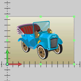
Notice the Image-Old Car item is added to the BobART tree under Images.
Selecting a location
-
By default the UCS is set to Top(X/Y) which is the desired UCS for this example.
-
The bottom left of the image is placed at the Origin position.
This can be adjusted by editing the values in the fields, or by placing your mouse over the image and dragging it into the desired position.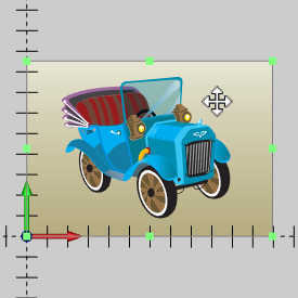
For this example, we leave the origin at 0 for all values. -
If needed we can add a rotation angle to the image, but keeping the edges parallel with the X and Y axis is the desired result in this case, so this value is left to 0 as well.
Setting the size
-
The current size of the image is listed as:
-
X Size = 11.9567
-
Y Size = 8.5300
-
-
These values can be updated by adjusting the values in the fields directly, or by using your mouse in the graphics area to pull the given points in the desired direction.
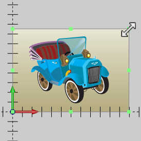
In this case we will leave the size as it is, but adjusting one of these values with either method automatically adjusts the other to keep the aspect ration of the image.To adjust a single value independently, clear the Keep Aspect Ratio check box.
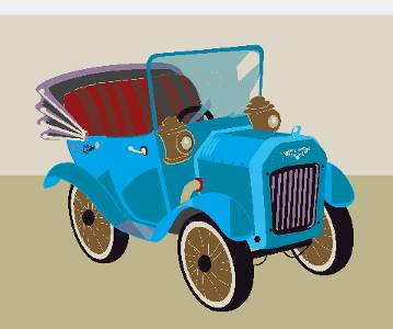
Setting the Transparency
-
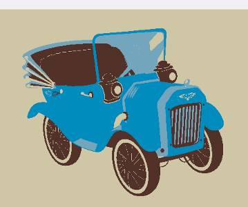
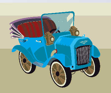
To adjust the transparency, in the Transparency group at the bottom of the dialog, select Full Image and either adjust the slider, or set the value between 0 and 1.
In the images below you will see the a value of 0, followed by a value of 0.75.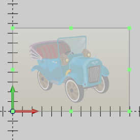
In this case we will leave the Transparency at 0. -
Ensure the Transparency is set to 0, and click OK.
Tip: When modifyingthe image this way, any previous vectorization result remains in the previouslocation.To update the results to the new location, you can simply openthe Vectorize... dialog and click OK.Alternatively, you can useany standard CAD functionality to move or modify the vectorizedgeometry.Any vectorization performed after moving the geometry, automaticallyuses the new location.
Part 3) Hiding and Showing the Image
When vectorizing images, you need to hide and show the image in orderto view and work with the geometry that is created.There are two waysto hide images, and it is important to understand how they work.
-
Click anywhere in the graphics area (to giveit key focus), and press I.
The letter I is the keyboard shortcut to hide all images.
Press I again and the image isshown. -
In the Quick Access Menu at the top of the BobART tab, click the
 icon.
icon.
All images in the graphics area are hidden.
Repeat the process and all images areshown. -
Right-click on
Images and select Blank/Unblank All.
All images in the graphics area are hidden.
Repeat the process and all images areshown. -
Right-click
 Image-Old Car, and click Blank/Unblank.
The image is hidden.This method is used to hide or show a single image.
Repeat the process to show the image.
Note: For this example, you can use either methodto hide and show the image, since we only have a single image.Noticewhen hiding the image, the blanked icon ![]() displays next to the image iconin the BobART tree.
displays next to the image iconin the BobART tree.
Part 4) Using the Vectorize... dialog
This section explains how the Vectorize... dialog is used tocreate and modify the vectorized geometry.
The Multi-Color Strategy
In this section we begin using the multi-color strategy to vectorizethe image and begin exploring the various workflow options for creatingand saving geometry.
-
In the BobARTtree, right-click
Image-Old Car, and click Vectorize.
The Vector... dialog is displayed. -
In the Method group of the Strategy section, click Multi-ColorStrategy.
The image is shown divided into 64 specific colors.The multi-color strategy defaults the number of colors to 64, whichallows you to target very specific colors or color ranges in the imagein order to be more precise with the vectorization results.Experimentationwith the number of colors is an important aspect of learning to vectorizeimages in an efficient manner. -
Next to #of Colors, click the down arrow and select 64.
-
At the bottom of the Parameters group, under the color boxes, click CheckAll.
-
Click Apply to vectorize the image in its current state.

-
Next to #of Colors, click the down arrow and select 32.Notice the change in the preview.For example, the gradient of theimage background is reduced from 6 unique colors to 5, and the yellowand orange colors are removed from the head lights and the exhaust.
When you change the number of colors, the image is actually reducedto the selected number of colors, and the color boxes update underColors to be Vectorized.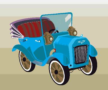
-
Continue reducing the #of Colors (for example to 16, 8, and 4), and observe the changein the preview.
-
Change the #of Colors to 24 andclick Check All to automaticallyselect the check box of all colors.
-
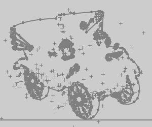
Click OKto vectorize the image.

The image is processed using all 24 colors to createthe vectorized geometry.Notice the horizontal lines.This is a resultof the gradient in the background of the image.The current settings separatedthe gradient into three unique colors.
Although it is not the method used for this tutorial,you could decide that you are now done with the vectorization and simplyedit the geometry.Depending on what you want to achieve, this may notbe the most efficient method to use.When using this method, you are vectorizingmany adjacent colors, which results in a large amount of entities.Regardlessof how you choose to work, we explore another important parameter next,Remove Chains Less Than.
Remove Chains Less Than
-
Next to
Image-Old Car,click  to expand the tree item.
To edit the parameters, right-click Vectorization,and click Edit.
Note: You can also right-click Image-Old Car, and click Vectorize.
-
In the Vectorize... dialog, set the # of Colors to 64.
-
Click UncheckAll.
-
Select the colors seen in the image below.

-
Click the
Blank Image button at the top-right to hide the image so we can better view the results. -
Click OK.
Notice that the geometry from the first vectorizationis removed and replaced with new geometry.
When there is geometry that you want to keep, you
Part 5) Copy Geometry to a New Layer to Save It
-
-
Press Ctrl+Cto copy the entities.
-
In the Layers Manager,right-click the layer name Grill and select Active Layer.
Confirm that the Active Layer icon is displayednext to Grill.
 -
Press Ctrl+Vto paste the entities onto the active layer.
-
In the Layers window, right-click the Grill layer and select Show Only This Layer.

-
Now that the geometry selection is confirmedto be correct, hide all but the CAD layer and set it as the active layer.
It is important that only the CAD layer is visible (for the processthat we are using).
This assures that you are only seeing the results of the vectorizationand not the copied geometry. -
To cancel selection mode, right-click anywherein the graphics area, and clickCancel.
Tip: You can also pressEsc to cancel selection mode.
Part 6) Use the Black and White Strategy
The 2 Level Black and White Strategy
This section explains how the Vectorize... dialog is used tocreate and modify the vectorized geometry.We start by experimenting withthe 2 Level Black and White strategy, as it is a viable option for vectorizingcolor images or black and white images.The strategy simply determineshow the image is analyzed in order to create geometry.
-
In the BobARTtree, right-click
Image-Old Car, and click Vectorize.
The Vectorize dialog displays and the image appears in blank and white with only portions visible.
This is because in the Strategy section, the Method is set to 2 Level(Black/White) Strategy by default. -
In the ThresholdValue field, update the value to 40.
No noticeable change occurs. -
Update the value again, but this time, use 60.
Notice the preview of the image updates each time that you change thevalue.
You can also click and drag the Threshold Value slider, in small increments,and release (to accomplish the same task). -
Change the Threshold Valueto 140.
-
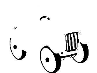
Click OK to vectorize the image
Hide the image to view the geometry.
The resulting geometry is -
To edit the vectorization we did, either:
-
Right-click
Image-Old Car, and click Vectorize... to enter the dialog again. -
Under
Image-OldCar, right-click Vectorization,and click Edit.
The Vectorization itemwas added to the BobART tree after the first vectorization.
-
-
Change the ThresholdValue to 174 and clickOK to update the vectorizationresult.

Notice that the geometry from the first vectorizationis removed and replaced with new geometry.
For this part, you experiment with the Black and White strategy to getthe profile of the car.
-
In the document toolbar, click
 to enable selection mode.
Press and hold Shift, and clickto chain-select the profile of the car as shown next.

-
Press Ctrl+Cto copy the entities.
-
In the Layers Manager,right-click the layer name Profile and select Active Layer.
Confirm that the Active Layer icon is displayednext to Profile.
This sets the layer to the active drawing layer. -
Pres Ctrl+V to Paste.
-
To confirm the geometry is properly pasted, right-click the Profile layer and select Show Only This Layer.
The geometry should appear as follows.
-
Hide all but the CAD layer and set it as the active layer.
Part 7) Continue Using the Multi-Color Strategy
-
Right-click
Vectorization,and click Edit. -
Select Multi-ColorStrategy.
-
Click the #of Colors arrow, and click 32.
Notice that the preview of the image changes based on the # of Colorsselected.
When you change the number of colors, the image is actually reducedto the selected number of colors, and the color check boxes are alsoupdated under Colors to be Vectorized.
Repeat this process of reducing the # of Colors (for example to 16,then 8, then 4, etc.) and observing the image preview.
This process is very helpful when trying to vectorize only a certainarea of the image. -
Set the #of Colors to 24.
Click Uncheck All.
Click to select the top check box in column 2 of Colorsto be Vectorized.
Click OK.
-
When you zoom-in to view the front wheel,you can see that there are small unwanted entities as shown next.

Part 8) Remove Chains Less Than
Remove Chains Less Than
The Remove Chains Less Than parameter is very important when vectorizingimages, as it helps you to remove unnecessary geometry that may be createdfrom the gradients in an image.
-
Show the image, and zoom-in closely to differentareas of the image and notice the geometry as compared to the selectedcolors (gradients).For example, the grill on the front of the caror the wheels are a great place to view how the geometry is createdbased on the colors.
The following image shows the colors of the front grill zoomed in closelywith the geometry hidden from view.You can see that there are actuallythree colors that make the vertical black and gray stripes.
Because we have vectorized all 24 colors, the software created geometryfor each color.The first point here is that you may not want to vectorizeadjacent colors, as it results in what appears as duplicate geometry,although it isn't.It may be better to vectorize only one of the colors.The second point is that the darker gray color results in very smallentities that are most likely not needed.The geometry from our vectorizationis shown next highlighted to make it easier to view.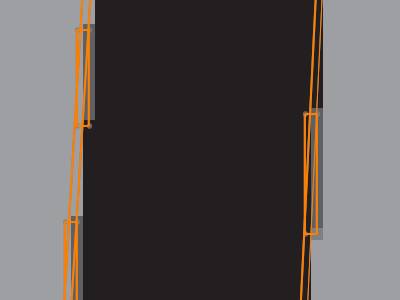
You can see the small rectangles are not needed, so now we use theRemove Chains Less Than parameters to remove them. -
Right-click Vectorization,and click Edit.
-
Under VectorizeParameters, change the RemoveChains Less Than value to 75(pixels), and click OK.
You can see that the small groups of entitiesare now removed from the result.You can experiment with the Remove ChainsLess Than value to make the vectorization result more efficient.Nextwe explore more ways to be efficient with vectorization.
-
In the document toolbar, click
to enable selection mode. -
In the graphics area, click and drag a window around the three wheels asshown next.


-
Copy the selected geometry, to the Wheels layer.(Useeither method as explained earlier.)
-
Hide all but the CAD layer and set it as the active layer.
Note: To getthe other contours from the wheel, the following color is used.
The Remove Chains Less Than value was changed to100, to create the following result.
Be sure to reduce the Remove Chains Less Than value(if needed) when moving on to vectorize a new area of the image.
Part 9) Edit the Vectorization Parameters
In this part, the seat is the target area from which you create geometry.
-
Right-click Vectorization,and click Edit.
-
Change the #of Colors to 20.
-
Select the following colors.

-
In the Remove Chains Less Thanbox, type 100.
-
Click OK.

The result appears as though some of the geometry is missing from theseat.To confirm if this is correct, show the image, and compare theimage and the geometry.You may want to hide and show the image afew times as you examine certain areas.You can see that the geometryfrom the seat is accurate (the steering wheel and the windshield causethe missing areas.)
You could window select the (seat) geometry and copy it to a new layer,but you would get double entities that need to be cleaned up later.In the following steps, you edit the vectorization and get the seatgeometry in two steps.This again helps you to get clean geometrythat requires less editing later. -
Edit the vectorization, and click to clear thebottom-left check box.

-
Click OK.

You can see that now you have much cleaner results.
Show and hide the image a few times to compare the image and the geometry.
The result is grabbing mostly the brown areas of the seat. -
Use chain-selection to select the desiredgeometry, and copy it to the SeatBrowns layer.


-
Use chain-selection to select the desired geometry, and copy it to the Seat Reds layer.

-
Edit the parameters, and select the following colors.

Click OK.
This time mostly the red areas of the seat are vectorized.
Show and hide the image to compare. -
Copy the desired geometry (remember to usethe chain-selection method), and paste it to the SeatReds layer.

The brown areas of the seat are copied to the SeatBrowns layer.
All of the geometry created so far is shown next.
-
Continue this process until you have createdall of the desired geometry from the image.
(Pick a target area.Adjust the Number ofColors to create the desired results.Copy the geometry to a new layer,and repeat.)

Final Notes
Image Origin
You can change the location of the image in the graphics area using theImage Origin dialog.
To change the image location:
- Right-click Image-name, and click Edit.
- Set the Origin values (inrelation to the WCS or world coordinate system).The Origin of theimage is the lower-left corner.
- Click OK.The image ismoved.
- To move any vectorized geometry to the new location, open the Vectorize... dialog, andclick OK.
Warning: Only the original geometry associated to the image, and not copies of the geometry will be updated using this method.
Moving the image is helpful when you vectorize more than one image.
Image Size
In the Vectorize... dialog, the Image Size values are used toscale the vectorized geometry that is created.(The size of the imageis not actually changed.)
Remove Arcs
If you want to create the vector geometry using only line segments,clear the ![]() With Arcs check box in the Vectorize...dialog.
With Arcs check box in the Vectorize...dialog.
Vectorize Parameters - Accuracy
The Accuracy parameter can be changed to create smoother or roughercontours.
High Accuracy (0.10 pixels)

Low Accuracy (0.90 pixels)

This concludes the tutorial.