


Lathe Basics Tutorial
Introduction
This tutorial is designed to highlight some of the key areas of the lathe module. In this example, we will be working on both the OD, and the ID. Operations will include Turning, Grooving, and Threading.
Example File
If you are connected to the Internet, the part file for this example can be downloaded automatically by clicking the following link: Lathe_Basics_Tutorial BBCD.zip
Once you download and saved the zip file, extract the files on your system in an easy place to remember. You can then open the file to use with this tutorial. All files for the tutorials in this help system available for download can be found by clicking on the following link: http://www.bobcad.com/helpfiles.
This tutorial highlights the following features of the BobCAD-CAM software:
- Create a Turning Job
- Creating Stock and Adjusting Visibility
- Creating Lathe Features
- Lathe End Face
- Lathe Turning (OD and ID)
- Lathe Groove (OD and ID)
- Lathe Thread (ID)
- Creating Feature Settings
- Adding Extensions
- Selecting a Tool
- Adjusting Parameters
- Blanking Toolpath
- Selecting Geometry
- Setting Machining Strategies
- Setting Parameters
- Setting Patterns
- Opening and Closing Simulation
- Posting the Program
Part 1) Open the Example File and Create a Turning Job
For every turning part that is created, you will need to open or create the lathe part and then create a Turning Job. In this case, we will be opening an existing CAD file to create a Turning Job.
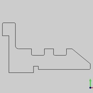
Important: The wireframe geometry is flat in the X/Y plane and in the X-/Y+ quadrant. When creating a Turning Job, this is the quadrant in which your geometry should be located.
- Open the Lathe_Basics_Tutorial.
- Click the CAM
Tree tab.
- Right-click
 CAM Defaults, and click New Job.
 - Under Job
Type, select Turning
The Stock Wizard displays.
Part 2) Creating Stock and Adjusting Visibility
The first page of the Stock
Wizard allows you to define a Workpiece for the Turning Job and the subsequent
pages handle shape, size and clearances. In this example, we will
not define a Workpiece, but will define the shape, size and clearances
for our stock. Once the stock has been defined you can adjust the visibility
of the stock.
- Click

For more information on assigning a Workpiece, see the Assigning Workpiece Geometry topic. - In the Stock Type page, leave the selection on Cylindrical.
- In the
Size group, type in the following
values:
- Stock Diameter = 5.125
- Internal Diameter = 1.000
- Length = 6.000
- Stock Origin = 0.125
- Click .
- Leave the Clearance values as they are and click OK
to finalize the stock and exit the wizard.
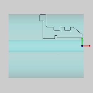
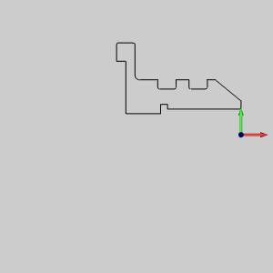
- In the CAM
Tree tab in the BobCAM CAM Tree, right-click
 Stock
and select either Transparency
or Blank. These choices will
allow you to, either adjust the transparency of the stock or blank
it out completely.
Stock
and select either Transparency
or Blank. These choices will
allow you to, either adjust the transparency of the stock or blank
it out completely.
|
Higher Transparency |
Blank |
|
|
|
Part 3) Facing the Part
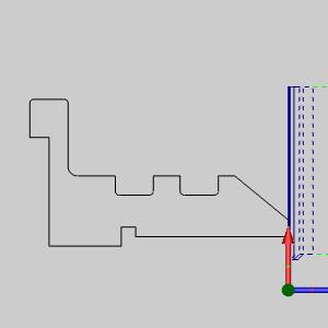
For most every Turning Job, you will need to face off the stock. By selecting a Lathe End Face feature, we will automatically create toolpath up to the machine zero without the need to select geometry. The only time geometry will need to be selected for the Lathe End Face feature is if the desired toolpath needs to end before, or, continue beyond the machine zero.
Add the Feature
- In the CAM Tree, right-click
 Machine Setup - 1 and select
Lathe End Face.
Machine Setup - 1 and select
Lathe End Face.
The Lathe End Face feature launches with the Geometry Selection page active. Since our target geometry is already at the machine zero, we do not need to select geometry. - Click Next>>
to continue to the Feature page.
Create Feature Extensions
- Select the Extension
check box and, in the End Distance
box, enter a value of 0.1000.
Tip: Since the Lathe End Face feature ends at the inner diameter of our stock, we use a small extension so our tool radius does not leave any material.
- On the left side of the Lathe Wizard, click
 Rough.
Tip: We select page options in the tree on the left side of the Lathe Wizard to skip pages with options we are not interested in adjusting.
Select a Tool
- Click Tool
Crib at the top of the Lathe Wizard.
The Tool Crib launches. - Click ROUGH to select the insert
type, and then click Add From Tool
Library.
The Tool Library launches. - Select tool number 263
to highlight the CNMG
- 3/64RAD - ROUGH TURNINGtool.
- Click OK
to exit the Tool Library and return to the Tool Crib.
- Click OK
to exit the Tool Crib and return to the Lathe Wizard.
- Select
 Parameters.
Adjust Parameters and Compute
- Select the Rough Allowance check box.
Tip: In this case, we use our roughing tool to rough and finish the face. Since we use the same tool for the rough and finish, the need to create a separate finish operation is avoided by utilizing the Rough Allowance. The Rough Allowance ceases the roughing operation at the values entered and creates an additional semifinish pass up to the Finish Allowance specified next.
- In the Finish Allowance
group, change both the Z and, X value to 0.0000.
Tip: By setting our Finish Allowances to 0.0000, the semifinish pass we take acts as a final finish.
- Since no other options need to be adjusted for this operation,
click Compute.
Blank Toolpath
- So that we can focus on one toolpath at a time, right-click the new Feature Lathe End Face in the CAM Tree and select Blank/UnblankToolpath to hide the toolpath.
Part 4) Turning the Part
In this step we create a Lathe Turning feature, assign Rough and Basic Finish operations, and define the parameters of those operations.
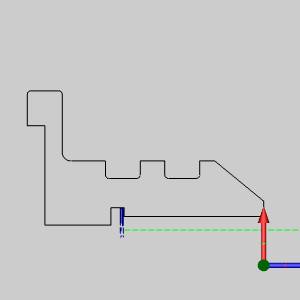
Add the Feature and Select Geometry
- In the CAM Tree, right-click Machine Setup - 1 and select
Lathe Turning.
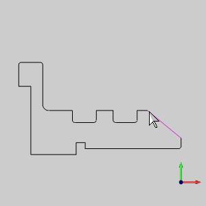
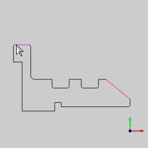
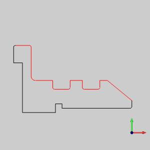
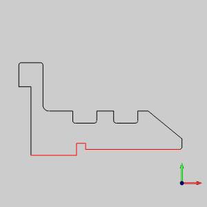
The Lathe Wizard launches with the Geometry Selection page active. - Click Select
Geometry.
The Lathe Wizard hides and the -
-
The geometry is added to the list. -
- Click
 OK to confirm the geometry selection and return to the Lathe Wizard.
Tip: To confirm geometry
selections, you can also click the ![]() icon in the toolbars or simply press Spacebar.
icon in the toolbars or simply press Spacebar.
|
Left-click |
Shift + Left-click |
Result |
|
|
|
|
- In the Lathe Wizard, click Next>> to continue to the Feature page.
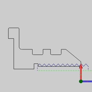
Adjust Feature Settings
- In order to avoid cutting the grooves with
these operations, select the Remove
Primary Undercut check box in the Undercut
group.
- To continue beyond the selected geometry,
select the check box for Extension
and enter a value of 0.2500
into the End Distance box.
- Click Next>> to continue to the Machining Strategy page.
Set the Machining Strategy
- Select Rough
/ Finish in the Machining Strategy
section of the Machining Strategy page to assign a Rough and Basic
Finish operation to the feature.
- Select Parameters.
Adjust Parameters
- Adjust the Z
value of the Finish Allowance
to 0.0010.
- In the Bounds group,
select the Trim
to Stock check box.
- Click the Apply to All Operations button to apply the trim to the finish pass as well.
- Select
 Finish.
Tip: In this case, our stock has already been faced off. In order to avoid unnecessary feed movement, we use the Trim to Stock option to set trim the toolpath to the Operation Stock.
Select a Tooland Compute
- Click Tool
Crib.
The Tool Crib launches. - Click FINISH and then click Add
From Tool Library.
The Tool Library launches. - Select tool number 277
to highlight the VNMG
- 1/32RAD - FINISH TURNINGtool.
- Click OK
to return to the Tool Crib.
- Click OK
to return to the Lathe Wizard.
- Click Compute.
Blank Toolpath
- Right-click the new Feature Lathe Turning in the CAM Tree and select Blank/Unblank Toolpath.
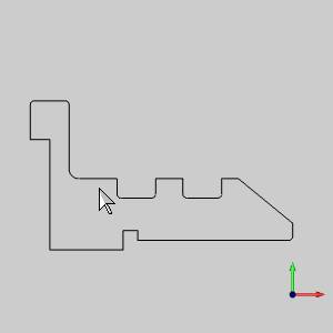
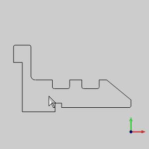
Part 5) Grooving the OD
In this case, we have two grooves that need to be completed on the OD of the part and one groove on the ID. Right now we will focus on the two OD grooves.
Add the Feature and Select Geometry
- Right-click Machine
Setup - 1 in the CAM Tree and select
Lathe Groove.
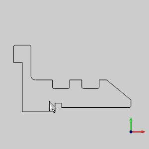
The Lathe Wizard launches. - Click Select
Geometry.
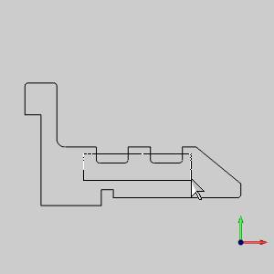
- In the graphics area:
-
-
Both grooves are highlighted. - Click
 OK.
OK.
|
Left-click + Hold |
Drag Window and Release |
Result |
|
|
|
|
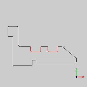
- Click Next>>
to continue to the Feature page.
Adjust Feature Settings and Select a Tool
- In the Feature page, under the Constraints
section, select From Geometry.
- Select
 Groove.
 - Click Tool
Crib.
The Tool Crib launches. - Click GROOVE and then click Add
From Tool Library to enter into the Tool Library.
The Tool Library Launches. - Select tool number 281
to highlight the 1/8 WIDE - 1/64RAD
- OD GROOVE tool.
- Click OK.
- In the Tool Crib, click OK.
- Select
Patterns.
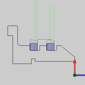
Set Patterns, Parameters and Compute
- Select Center
Out under Sorting and
click Next>> to continue
to the Parameters page.
- Select the check box for Rough
Allowance and adjust the X
value to 0.0050.
- Under Semifinish
Pattern, set the Overlap
value to 0.0050 to ensure
that each of the downward semifinish cuts will go slightly beyond
center.
- Set the Finish
Allowance values to 0.0000.
- Click Compute.
- Right-click the new Feature
Lathe Groove in the CAM Tree and select Blank/Unblank
Toolpath.
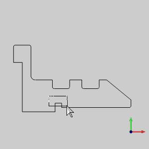
Part 6) Boring the ID
Now that we have completed the outer diameter of the part, we need to begin working on the inner diameter. The first thing we will work on is a basic Rough and Finish.
Add the Feature and Select Geometry
- Right-click
Machine Setup - 1 in the CAM Tree and select Lathe
Turning.
The Lathe Wizard launches. - Click Select
Geometry.
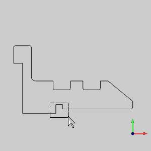
In the graphics area:- Drag a window
around the entire groove. The groove and connected entities highlighted.
- Press
confirm the geometry selection.
|
Left-click + Hold |
Drag Window and Release |
Result |
|
|
|
|
- Click Next>> to
continue to the Feature page.
Set Feature Settings
- In the Feature page under Material
Approach, set the Rapid Plane
to 0.0500.
- Under Feature
Parameters, select ID
from the Feature Type list
to set the orientation of the feature.
- Under Undercut,
select the Remove Primary Undercut
check box so that our rough does not try to complete the ID groove
feature.
- Select the check box for Extension
and enter a value of 0.4500
into the End Distance box.
- Select
Rough.
Select a Tool
- Click Tool
Crib.
The Tool Crib launches. - Click
 BORING and then click Add From Tool Library.
The Tool Library launches. - Select tool number 500
to highlight the CNMG
- 1/32 RAD .750 BORING BARtool.
- Click OK.
- In the Tool Crib:
- Notice the orientation of our ID boring tool in
the graphics area in the top right corner of the Tool Crib.
- In order to have this tool orientated properly,
select
 under Mounting
Orientation.
under Mounting
Orientation. - Notice the tool and its holder is now in the proper
orientation.
- Click OK.
- Select Parameters.
Set Parameters, Leads and Compute
- In the Parameters page, select the check
box for Rough Allowance and
adjust the Z value to 0.0010.
- Set both Finish
Allowance values to 0.0000.
- In the Bounds group, select the Trim to Stock check box.
Tip: In this case, our stock has already been faced off. In order to avoid unnecessary feed movement, we use the Trim to Stock option to set trim the toolpath to the Operation Stock.
- Select Leads.
- Under Lead-out, set
the Length value to 0.0500.
- Click Compute.
Blank the Toolpath
- Right-click the new Feature Lathe Turning in the CAM Tree and select Blank/Unblank Toolpath.
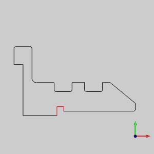
Part 7) Grooving the ID
Now that we have cleared out the ID with our ID Turning feature, we can work on the ID groove.
Add the Feature and Select Geometry
- Right-click
Machine Setup - 1 in the CAM Tree and select Lathe
Groove.
The Lathe Wizard launches. - Click Select
Geometry.
In the graphics area:- Drag a window
around the entire groove. The groove and connected entities highlighted.
- Press
confirm the geometry selection.
|
Left-click + Hold |
Drag Window and Release |
Result |
|
|
|
|
- Click Next>> to
continue to the Feature page.
Set Feature Settings
- In the Feature page, under Material
Approach, set the Rapid Plane
to 0.0500.
- Under Feature
Parameters select ID from
the Feature Type list.
- Under Constraints,
select Custom and then click
Pick since the material has
already been removed for a portion of this geometry, we can change
where the toolpath begins.
The Lathe Wizard hides and the dialog opens allowing geometry selection.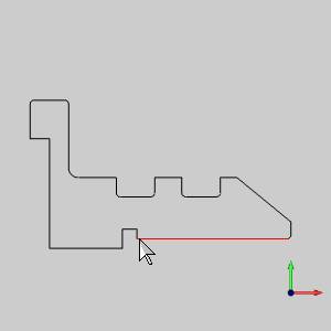
- Highlight the
- Confirm the geometry selection.
The Lathe Wizard returns. - Select Groove.
Select a Tool
- Click Tool
Crib.
The Tool Crib launches. - Click GROOVE and then click Add
From Tool Library.
The Tool Library launches. - Select tool number 280
to highlight the 1/8 WIDE - 1/64RAD
- ID GROOVE tool.
- Click OK.
In the Tool Crib: - Select
 under Mounting Orientation.
 - Click OK.
- Select Parameters.
Set Parameters and Compute
- Select the check box for Rough
Allowance and adjust the X
value
to 0.0500.
- Set both Finish
Allowance values to 0.0000.
- Click Compute.
Blank Toolpath
- Right-click the new Feature Lathe Groove in the CAM Tree and select Blank/Unblank Toolpath.
Part 8) Creating the ID Thread
Now that the ID has been cleared out, we will need to create the threading operation on the ID.
Add the Feature and Select Geometry
- Right-click
Machine Setup - 1 in the CAM Tree and select Lathe
Thread.
The Lathe Wizard launches. - Click Select
Geometry.
In the graphics area:- Drag a window
around the entire groove. The groove and connected entities highlighted.
- Press
confirm the geometry selection.
- Click Next>> to
continue to the Feature page.
Set Feature Settings
- In the Feature page, under Feature
Parameters select ID
from the Feature Type list.
- Select the check box for Extension:
- In the Start
Distance box enter a value of
- In the End
Distance box enter a value of 0.0300.
- Select
 Thread.
Select a Tool
- Click Tool
Crib.
- Click THREADING and then click Add From Tool Library.
- Select tool number 505
to highlight the 60 DEG - LAY DOWN - ID THREAD .IC tool.
- click OK.
- In the Tool Crib:
- select under Mounting Orientation.
- Click OK.
- Select Parameters.
Set Parameters and Compute
- Under Parameters,
set Threads Per Unit to 5.0000.
- Select the check box for Override and set Thread Height to 0.1190.
Important: The Thread Height that is calculated in BobCAD-CAM is the theoretical sharp height. Depending on the thread being cut, you may need to adjust this value.
- Click Compute.
Blank Toolpath
- Right-click the new Lathe Thread feature in the CAM Tree and select Blank/Unblank Toolpath.
Part 9) Simulation
The next step is to simulate the program to look for any necessary changes.
Open and Close Simulation
- In the Modules
menu, click
 Simulation.
For help with simulation, view Getting Started with Simulation.
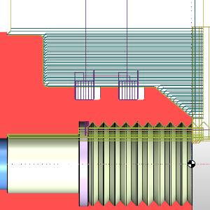
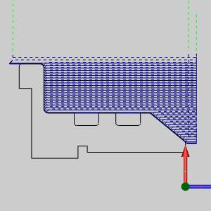
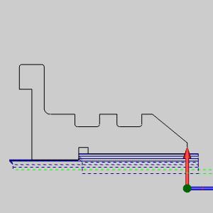
Tip: The
Simulation contains a CutSim tab.
Clicking on the ![]() Advanced Properties button will
launch the Parameters dialog box
allowing you to select the
Advanced Properties button will
launch the Parameters dialog box
allowing you to select the ![]() Enable check
box in the Section plane group.
This will put the stock in the section plane view seen in the image above.
Leave the values as they are and click OK.
Enable check
box in the Section plane group.
This will put the stock in the section plane view seen in the image above.
Leave the values as they are and click OK.
- To close simulation, click Modules>
 Exit Simulation.
Part 10) Posting the Program
Once the lathe result has been finalized it will be time to produce the code to send to the machine.
Post and Save or Edit
- In the CAM Tree, right-click
 Turning Job and select Post.
The code is posted in the Layer-UCS-Post Manager. - Right-click the code in the Layer-UCS-Post Manager
to select Save As or Edit CNC.
With this method, you can either save to a particular file location or open the NC code in Predator Editor respectively.
This concludes this tutorial.