


Break and Regroup Holes
Introduction
This topic provides an example of how and why to use Break Hole Groupand Regroup Holes for Mill drilling features.![]() Click here
Click here![]() to expand on the subject of Hole Groups.
to expand on the subject of Hole Groups.
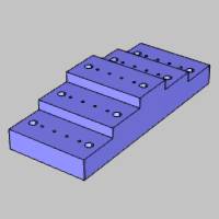
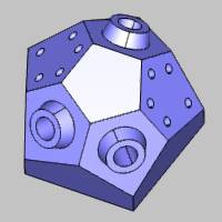

Part Model
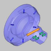
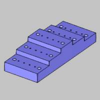
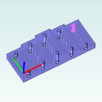
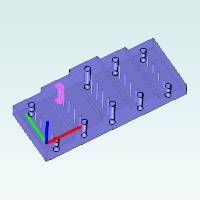
This example uses the following standard drilling part, but this informationcan be applied to all drilling types.
Toolpath
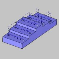
After creating a Mill Hole feature and selecting all of the holes inthe model, two features are created with the following toolpath result.

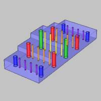
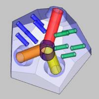
Hole Groups
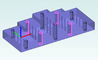
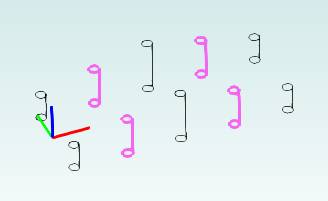
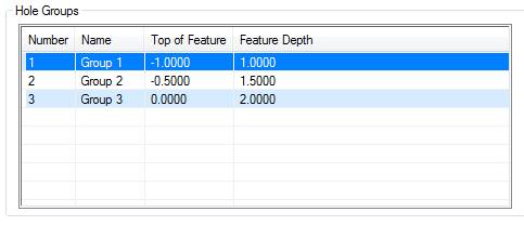
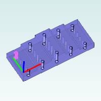
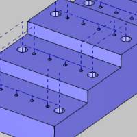
For reference, the following image shows all hole groups that the softwareautomatically creates, using one color for each group.All holes in asingle hole group must share the same diameter, top of feature, and featuredepth.

Why We Use Break Hole Group
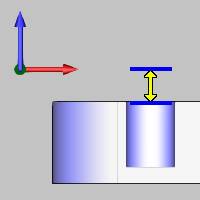
With hole groups, the rapid plane value determines the rapid movementwithin a hole group.The group retracts, however, determine the rapidmovement between hole groups.
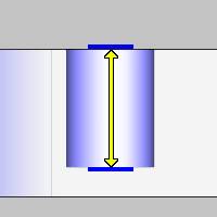
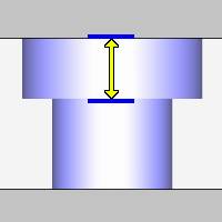
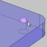
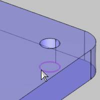
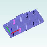
With the example part and toolpath shown, the rapid plane used withinhole groups is not clearing the steps of the model when moving from oneside of the part to the other.This is shown in the following images.
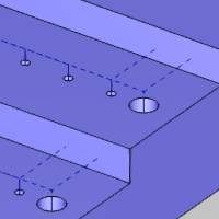
Although the rapid plane value could be increased, we want to make ourtoolpath as efficient as possible, and doing so would cause a lot of extramovement within hole groups.For this reason, we use Break Hole Groupto separate the hole groups that contain holes on opposite sides of thepart.The result is that group retracts are used between the new groups,thus clearing the steps of the model and creating a more efficient toolpath.
Using Break Hole Group and Regroup Holes
Now we edit the feature and modify our hole groups on the Feature pageof the wizard.
-
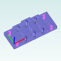
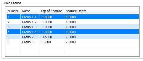
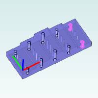
First, we select a group in the Hole Groupslist to show the preview of the group in the dialog box.
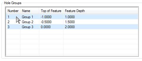
Note that you can click anywhere in a rowto select a group, but if you click the Name, Top of Feature, or FeatureDepth value, it becomes available for editing.(Either way, the groupis selected when the row displays in dark blue.)
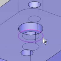
The Hole Groups preview displays directlyinside the dialog box to make it easy to visualize the groups.The Group1 preview is shown next.
Tip: Use themouse directly inside the Hole Groups preview window to control the viewingorientation as follows:
• Click and drag to rotate the view(you can use the left or middle mouse button).
• Use the scroll wheel (middle mousebutton) to zoom in or zoom out.
• Hold Ctrland drag the middle mouse button to pan the view.
-
With Group 1 selected, we click the BreakHole Group button.
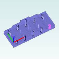
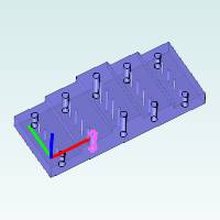
Group 1 is separated into four single-holegroups as shown next.Again, we select the group in the Hole Groups listto display the preview.
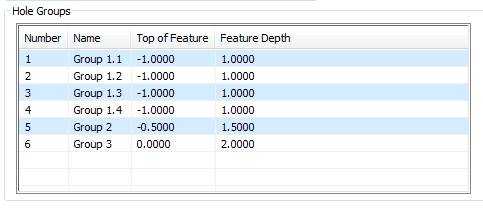
Notice the naming of the new groups: Group1.1, Group 1.2, Group 1.3.This makes it easy to manage the newly createdhole groups.
|
Group 1.1 |
Group1.2 |

|
|
|
Group 1.3 |
Group1.4 |
|
|
We can see that we want to regroup Group1.1 and Group 1.4 as well as Group 1.2 and 1.3.
-
In the Hole Groups list, we click Group1.1 to select it.
Next we press and hold the Ctrlkey, and click Group 1.4 to selectboth groups.
Tip: You multi-selectitems in the Hole Groups list using the Shift and/or Ctrl keys.Hold Ctrl and click a group to add itto or remove it from the current selection.Hold Shiftand click a group to select all groups between the first and second selections.(When removing selections using Ctrl, click the row of a group in theNumber column.)
-
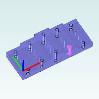
With both Group 1.1 and Group 1.4 selected, click the Regroup Holes button to create anew group from the selections.
Important: Whenusing Regroup Holes, the Top of Feature and Feature Depth must be thesame for all selected groups.For this example, the values are alreadycorrect for all groups, but you can edit the values directly in the HoleGroups table, if needed, before clicking Regroup Holes.
The software uses the name of the lowestnumbered group, so our new group is named Group1.1.
In the list, click Group1.1 to show the preview and confirm the proper grouping.
-
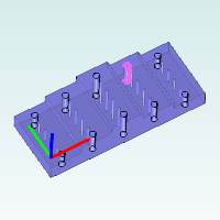
Group 1.2 and Group 1.3 are regrouped next using the same process.
-
The exact same process is used to break Group 2 and then regroupthe holes that are on the same side of the part.
|
Group 2 |

|
Breaking Group 2 resultsin the following groups.
|
Group 2.1 |
Group2.2 |
|
|
|
Group 2.3 |
Group2.4 |
|
|
Group 2.1 and Group 2.4 are regrouped tocreate a new Group 2.1.
Group 2.2 and Group 2.3 are regrouped tocreate a new Group 2.2.

-
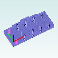
Finally, we compute the toolpath to update the changes madeto the hole groups.
(The hole groups in the second feature areregrouped to match what we did in the first feature.)
The second image shows that the toolpathnow properly retracts between each hole group and clears the steps ofthe model resulting in a more efficient toolpath.
This concludes the example.