


How to Create a 4 Axis Rotary Feature
Introduction
This tutorial provides an example of how to create a 4 Axis Rotary feature.This tutorial is supplemental to The 4 Axis Rotary Operation.
This tutorial explains the following functionality of the 4 Axis Rotaryfeature:
- How the toolpath is applied to the part
- Limiting the toolpath along the rotary axis
- Creating multiple depths (offset from the geometry)
- Using the Cut Interval option to determine the plunge location
- The importance of properly setting the Base Point and Directionparameters based on the rotary axis and machining origin
- Properly setting the Work Offset shift values for simulation
Example File
If you are connected to the Internet, the part file for this example can be downloaded automatically by clicking the following link: 4 Axis RotaryExample 1.bbcd
Once you download and saved the zip file, extract the files on your system in an easy place to remember.You can then open the file to use with this tutorial.All files for the tutorials in this help system available for download can be found by clicking on the following link: http://www.bobcad.com/helpfiles.
In the example file provided,the stock and Machine Setup are already defined for the part.The programis simulated using the BC 4x Mill, which is a 4-axis machine with an A-axisrotary.
Part 1) Add the Feature
-
Open the example file: 4Axis Rotary Example 1.bbcd
-
In the Data-CAMTree Manager, click the CAM Tree Manager tab.
-
To add a feature, right-click
 Machine Setup,and click Mill 4 Axis Rotary.
The Mill 4 Axis Rotary Wizard displays.
Part 2) Select Geometry
- Under GeometrySelection, click Select Geometry.
The Mill 4 Axis Rotary Wizard hides and the Feature Geometry Picking dialog opens in the Data Entry tab. - Click and drag a window to select the entire part.

 `
` -
To confirm the selection, click OK.
The Mill 4 Axis Rotary Wizard reappears. -
Click Next>>to begin editing the Feature parameters.
Part 3) Define the Feature Parameters
-
In the Feature settings, notice that theClearance Plane is automaticallyset using the value from the Machine Setup.
-
Change the RapidPlane to
-
Change theFeed Plane to
-
The Topof Feature is automatically set (0.000) based on the selectedgeometry and machining origin.
-
Click Next>>to go to the Machining Strategy.
Part 4) Define the Machining Strategy
-
Confirm that there is one 4Axis Rotary operation in the CurrentOperations list.
(You can add one or more 4 Axis Rotary operations to a single feature.) -
No other changes are needed.
Click Next>>to go to the Posting settings.
Part 5) Define the Posting Parameters
-
The Work Offset # is automatically set tothe value previously defined in the Machine Setup.
You can update the Work Offset # for the feature here when needed. -
Click Next>>to go to the Multiaxis Posting settings.
Part 6) Define the Multiaxis Posting Parameters
-
Notice, at the top of the dialog box, that the Use Machine Settings checkbox is selected.
This means that the Multiaxis Posting parameters for the feature usethe same parameters as the machine that is selected in Current Settings.
You can clear the Use Machine Settingscheck box to define the Multiaxis Posting parameters of the featureseparately from the current machine settings.
For this example, no changes are needed. -
Click Next>>to go to the Tool settings.
Part 7) Define the Tool Parameters
-
In the ToolData group, clear the
 System Tool check box.
Set the Diameter to
Set the Corner Radius to
We are creating a new tool because the default Tool Library doesn'talready contain a similar ball endmill. -
Click AssignTool Holder.
-
Under CAT40 Holder, click to select the 0.5inch I.D. Arbor CAT 40, and click OK.
-
To finish the tool definition, click Next>>.
Part 8) The Pattern Dialog Box
-
In the CutPattern group, to define one-way cutting, Zigis selected.
-
Next to Style,click the down arrow and select Around.
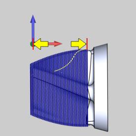
Important: Tocreate proper toolpaths with the Rotary feature, you must define the Direction and BasePoint for the rotational axisof the part.The Base Point values are based on the machining originlocation in reference to the center of rotation for the part.The following steps handle the machining origin at the top of the cylinder,as it is in this example.(If the machining origin is in-line with therotary axis, then the Base Point values are set to zero.Placing the machiningorigin on the rotational axis of the part means there is no differenceto report between the machining origin and the rotary axis.)
-
To set the direction of the rotary axis, under Rotary Axis, select XAxis.
Because the machining origin was moved awayfrom the center of rotation, the difference must be defined using theBase Point parameter.
The following image shows the distance thatis used to set the base point.This is the distance from (1) the machiningorigin to (2) the center of rotation of the part.
This parameter is an important part of propertoolpath creation.

(When the wizard is closed, you can click![]() Machine Setup in the CAM Treeto view the machining origin in the Workspace.)
Machine Setup in the CAM Treeto view the machining origin in the Workspace.)
The only difference to report for this exampleis along the Z-axis.The radius of the part (and stock) is 3.2679 inches.
-
Under Base Point, inthe Z box, type -
-
Click Next>>.
Part 9) The Parameters Dialog Box
-
In the Finishgroup, we use the default Stepovervalue of
-
To leave material for finishing, in the AllowanceXYZbox, type
For this example, we can increase the tolerance value of our roughingoperation to speed up calculation time.
Change the Machining Toleranceto -
To calculate the toolpath, clickCompute.

Notice that a single toolpath pass is createdthat follows the selected surfaces along the entire length of the part.
The next step is to edit the feature anduse the Along Rotary Axis options to limit the toolpath on the part.
Part 10) Edit the Feature and Limit the Toolpath
When you computed the toolpath, the 4 Axis Rotary feature was addedto the CAM Tree.Next we limit the toolpath calculation so that it doesn'tcut the entire part.
-
To edit the feature, in the CAM Tree, right-click
 Feature 4 AxisRotary, and click Edit.
 -
On the left side of the dialog box, clickParameters.
-
In the AlongRotary Axis group, select the
 Endcheck box, and type
This setting limits the toolpath to fourinches from the machining origin.
You can also limit the toolpath by changingthe Start parameter to define where the toolpath starts in relation tothe Machine Setup, along the defined Rotary Axis Direction.
Tip: You canuse the Along Rotary Axis parameters Start and End, to define where thetoolpath starts and ends.(By default, the Rotary feature creates thetoolpath by cutting in the positive direction along the selected rotaryaxis.For example, with a A-axis rotary (rotation around the X-axis) thetoolpath is from left to right.)

Part 11) Create Multiple Passes
The next step is to add multiple passes to the feature.
-
In the MultiplePasses group, select the
MultiplePasses check box. -
Under RoughingPasses, in the Numberbox, type 2.
In the Spacing box, type -
Next to SortBy, click the arrow and select Passes.
This causes the feature to cut each pass before moving on to the nextpass.In other words, this cuts the entire part to one depth beforemoving on to the next depth. -
To update the feature, click Compute.
The toolpath now contains two passes insteadof the single pass created earlier.
Notice that the multiple passes are created fromthe selected surface and are layered outward.(They are not layered fromthe stock inward.)


Part 12) Change the Cut Interval
Before simulating the program, there is one last change to make.Youcan see in the toolpath from the previous step that the tool is plunging,at rapid rate, into one of the deepest areas of the part geometry.Thenext steps cause the tool to plunge into a more shallow area of the part.
-
Edit the feature, and click Patterns.
-
Under AngularStart/End, select the CutInterval option.
-
In the AngleStart box, type -135.
-
In the AngleEnd box, type 225.
-
Click Compute.


Note: You can also use Angular Start/End to cut only a portion of the part should your Angle Start and Angle End values not be equal to 360° .
Part 13) Simulate the Program
-
To simulate the toolpath, right-click Milling Job, and click Simulation.
To learn more about simulation, view GettingStarted with Simulation.

Note: About the Toolpath Display - Rewinds:
When you simulate the program, you can seea large circle in the toolpath.This circle in the toolpath representsthe tool retracting during the machine rewinds that result from the rotationallimits set for the machine (in the Machine Definition of the Default CurrentSettings).Once the machine reaches its maximum rotational limit, therotary axis must rewind.The rewind can be seen in the middle of the programsimulation.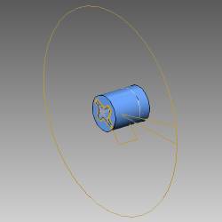
-
For this example, it is important to understand the Work Offsetparameter that was previously defined in the Machine Setup dialogbox.
To open the Machine Setup dialog box, in the CAM Tree, right-clickMachine Setup,and click Edit. -
In the Machine Setup dialog box, click WorkOffset and notice the XYZvalues.
These XYZ values represent the distance from the machine zero to thepart zero (machining origin) defined in the Machine Setup.For thisexample, this is from the center of the face of the rotary table (virtualmachine zero) to the machining origin that is on the top of the cylindricalstock. -
When the machining origin is not the same as the virtual machinezero, you must define the difference between these two coordinatesystems using the Work Offset dialog box.This is necessary to createthe proper machine simulation and posting.
To learn more about the 4 Axis Rotary feature,including Trim to Stock, view the 4 Axis Rotary Operation topic.
This concludes the tutorial.