


How to Create a Multiaxis Swarf Operations
Introduction
This tutorial explains how to create a Multiaxis feature with the Swarftoolpath.The goal of swarf milling is to create the desired cut usingthe entire flute length of the tool.This is great for machining fluidparts such as blisks (bladed disks) and impellers.
Example File
If you are connected to the Internet, the part file for this example can be downloaded automatically by clicking the following link: Swarf Example 1.bbcd
Once you download and saved the zip file, extract the files on your system in an easy place to remember.You can then open the file to use with this tutorial.All files for the tutorials in this help system available for download can be found by clicking on the following link: http://www.bobcad.com/helpfiles.
In the example file provided,the stock and Machine Setup are already defined for the part.The partis simulated using the BC Table-Table machine.
In this example, you learn how to select geometry and how to set thechain direction of each curve to create the proper results.This exampleuses the Automatic strategy and what is explained here can be appliedto the other Swarfing strategies.Adding leads, creating multiple steps,adding a gouge check, and an important note on machine movement are alsoexplained.

Part 1) Add the Feature
-
In the CAM Tree Manager, right-click
 MachineSetup and click Mill Multiaxis.
 -
In the MultiaxisWizard, select Swarf Machining.
-
Click Next>>to go to the Posting settings.
Part 2) Define the Posting Parameters
-
The Work Offset # is automatically set tothe value defined in the Machine Setup.
You can change the value here to update the Work Offset # for the feature. -
Click Next>>to go to the Multiaxis Posting settings.
Part 3) Define the Multiaxis Posting Parameters
-
Notice, at the top of the dialog box, that the Use Machine Settings checkbox is selected.
This means that the Multiaxis Posting parametersfor the feature use the same parameters as the machine that is selectedin Current Settings.
You can clear the UseMachine Settings check box to define the Multiaxis Posting parametersof the feature separately from the current machine settings.
For this example, no changes are needed.
-
Click Next>> togo to the Tool settings.
Part 4) Define the Tool Parameters
-
In the ToolData group, set the Diameterto 0.75 andset the Corner Radiusto 0.00 to automatically searchand load a tool from the Tool Library.
-
Click AssignTool Holder.
-
In the Milling Tool Holder Library, clickto select 0.750 inch I.D. Arbor CAT40, and click OK.
-
Click Next>>to go to the Parameters.
Part 5) Select Geometry
-
For this example, we are using the Automaticstrategy because it always uses a Swarf Surface selection, and wealso turn on the option to select the Upper Curve and Lower Curvegeometry.
These options allow the system to find the best fit of the tool withthe swarf surface and the upper and lower rail while allowing youto more easily define the cutting method (direction and side) as wellas the ability to gouge check the Swarf Surfaces. -
Under Geometry Selection, next to SwarfSurfaces, click
 .
.
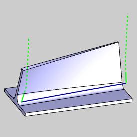
Select the swarf surface as shown next.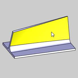
-
To confirm the selection, click OK.
-
Under GeometrySelection, click to select the GuideCurves check box.
-
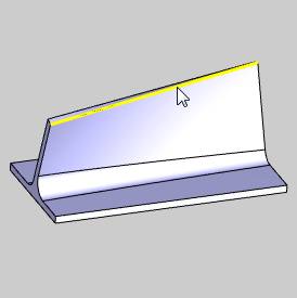
Click Upper.
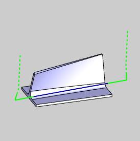
Select the upper curve as shown next.
(Be sure to select the surface edge and notthe top surface.)
To confirm the selection, click OK.
-
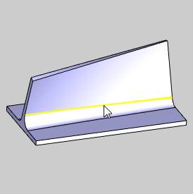
Click Lower.
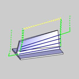
Select the lower curve as shown next.
To confirm the selection, click OK.
Note: The geometry selections for swarf machiningchange depending on the Strategy selected.With any strategy, you havethe option to select the Upper and Lower Curves which are used to alignthe tool.The curves are split into equal-length segments and the matchingpoints for each segment are used to create the tool orientation.Selectingthe Upper and Lower Curves gives you control of the cutting side and directionfor the feature.If you don't select the curves when using the Automaticstrategy, the system attempts to find the correct curves and cutting directionautomatically using only the selected swarf surfaces.
Part 6) Define the Parameters and Create the Toolpath
-
To leave material for finishing, in the Swarf Clearance box, type 0.30.
In the Machining group, nextto Side, select Left. -
At the top of the dialog box, click Link.
-
Click Retracts.
In the Clearance Area group, confirm thatthe Type is set to Plane,and the Direction is ZAxis.
Confirm that the Heightis set to 4.000.
This value is automatically set (but onlywhen the feature is created) using the Clearance Plane value from theMachine Setup.You can modify the Clearance Plane for the feature in thislocation at any time.
Click OK.
-
At the bottom of the wizard, click Compute.
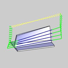
The result is shown next.
-
Notice that the toolpath computed on the wrong side of the part.
In the following steps, you change the CuttingSide to resolve this problem.You can also resolve this issue by reversingthe chain direction of the Lower Edge curve.The steps to do this arelisted at the end of the next section.
Part 7) Edit the Feature
-
To edit the feature, in the CAMTree, right-click
 Feature Multiaxisand click Edit.
 -
On the left side of the Multiaxis Wizard,click Parameters.
In the Machining group, nextto Side, click the down arrowand select Right. -
At the bottom of the dialog box, click Compute.
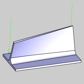
Tip: When selecting the Upper and Lower Curves, you can determine the MachiningSide using the chain direction of the lower curve as explained next:
• To view the StartPoint, in the CAM Tree,right-click ![]() Second/LowerEdge Curve and click Modify.(This is contained in the Geometry folder underthe Multiaxis operation.)
Second/LowerEdge Curve and click Modify.(This is contained in the Geometry folder underthe Multiaxis operation.)
• In the Workspace, the start point becomes visible.To change the start point, click near the end of the entity, and thenclick ![]() .
.
• In addition to the previous method, to reverse thedirection, you can right-click ![]() Second/Lower EdgeCurve, and click Reverse Direction.
Second/Lower EdgeCurve, and click Reverse Direction.
Part 8) Add Leads
Notice that the toolpath is plunging directly into the edge of the partgeometry.This is not the desired result for this example.(To simulatethe feature and review the result, right-click Milling Job and click Simulation.)Next, you add a lead-in and a lead-out to cause the tool to plunge outsideof the part, so that the side of the tool is used to begin the cut.
-
In the CAMTree, right-click
Feature Multiaxis,and click Edit.
On the left side, click Parameters.
Click the Link tab. -
In the Entry/Exitgroup, next to First Entry,(on the right side) select Use Lead-In.
Next to UseLead-In, click ![]() to open the Lead-in dialog box.
to open the Lead-in dialog box.
Notice at the top of the dialog box, thatthe ![]() Use DefaultLead-In check box is selected.
Use DefaultLead-In check box is selected.
Click OK.
-
In the Entry/Exit group,next to Last Exit, (on theright side) select Use Lead-Out.
-
At the bottom of the dialog box, click DefaultLead-In/Out.
In the Lead-In group, nextto Type, select TangentialLine.
At the top of the dialog box, next to Copy,click .
.
Click OK. -
Click Compute.
The result is shown next.
-
To view the result, in the Modulesmenu, click
 Simulation.
To learn more, view GettingStarted with Simulation.

-
To close simulation, in the Modulesmenu, click
 Exit Simulation.
Part 9) Create Multi Cuts
Now instead of cutting the part with a single slice, multiple slicesare created using Multi Cuts.
-
Edit the feature, click Parameters,and click the Multi Cuts tab.
In the PatternSlices group, in the Depth Stepsbox, type 4.(By Numberof Slices is selected by default.)
Click Compute.
- Notice that the retract moves are again within the bounds of thepart.(This is for all links that are not the first entry or the lastexit.)
To change this result, edit the feature, and click the Linktab. - In the Links Between Slicegroup, next to Large Moves,select Use Lead-In/Out (onthe right side).
- Click Compute.
Now all depth steps use the same lead-in and lead-out as the firstentry and last exit moves. - Simulate the feature again to view the changes.
New to Swarf, you can now define Extensionsfor the toolpath in addition to, or instead of using leads.You can definethe length to extend the start and end of the toolpath separately or youcan define a starting angle from the swarf surface for the start of thetoolpath.This is shown at the end of this tutorial.
Part 10) Add a Gouge Check
There may be times when you want to use Swarf machining even thoughthe machining surfaces are not truly flat.This could result in gougingthe surface if the feature is defined too close to the target surface.In such a scenario, you can use a Swarf feature to get as close as possibleto the target surface before applying a different strategy to finish thepart.The Gouge Check can be used to push the tool out of swarf, or awayfrom the target surface.This means that the tool is moved away from thesurface by drawing a line between the contact points of the upper andlower rail; the tool is moved away at a right angle to this line.
-
Edit the Multiaxis feature, click Parameters,and click the Gouge Checktab.
-
In the Gougeand Excess group, next to Check,select Swarf Surfaces.
(You must have selected at least one Swarf surface to use this check.)
Confirm that the Degouge optionis selected next to Collision Handling. -
If there are additional surfaces that youwant to gouge check, you can select AdditionalSurfaces or Swarf and AdditionalSurfaces for the Gouge and Excess Check setting.(These sameoptions are also available under the Avoidby Relinking and Avoid byRetracting groups.The names of these groups determine howthe tool is moved to avoid gouges (relink or retract.)
-
After selecting any option that includesadditional surfaces, the geometry selection button displays.Click
, select the geometry togouge check, and click  .
.
This can be the part geometry or any other geometry. -
You can also define the amount of clearancefor the tool holder in the Clearances group.
-
To update the feature toolpath, click Compute.
Part 11) Minimize Table Rotations
When creating Swarf features, there may be fast machine movements thatcan be minimized.The following option is provided to help reduce thesemovements.
-
Edit the Multiaxis feature, click Parameters,and click the Tool Axis Controltab.
-
Select the
 MinimizeRotation Axis Changes check box.
 -
To update the change, click Compute.
-
To view the result, on the Othertoolbar, click the
 (Simulation) icon.
For this example, the amount of machine movement,specifically the table rotation, is greatly reduced.
Part 12) Add Extensions to the Toolpath
-
Edit the feature and click Parameters.
-
At the bottom of the dialog box, in the Extensions group, type 1.00in both the Start and End boxes.
This extends the lead-in and lead-out by the specified value.(Youcan use these options with or without leads defined for the feature.) -
Compute the toolpath.

This concludes the tutorial.