


How to Create a Multiaxis Wireframe Operation
Introduction
This tutorial explains how to create a Multiaxis feature with the Wireframetoolpath.The wireframe toolpath requires a Drive Curve selection to definethe toolpath and Orientation Lines selection along the curve to definethe tool orientation.
Example File
If you are connected to the Internet, the part file for this example can be downloaded automatically by clicking the following link: Multiaxis WireframeExample 1.bbcd
Once you download and saved the zip file, extract the files on your system in an easy place to remember.You can then open the file to use with this tutorial.All files for the tutorials in this help system available for download can be found by clicking on the following link: http://www.bobcad.com/helpfiles.
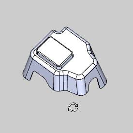
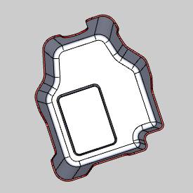
In the example file provided,the stock and Machine Setup are already defined for the part.The partis simulated using the BC Table-Table machine.
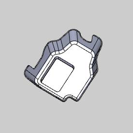
In this example, you apply a trim cut to the bottom surface of the part.This example explains how to create all the geometry that is needed forthe feature directly from the part model.You also learn how the chaindirection of the drive curve and orientation lines define the toolpath.An important section here explains how to set the side tilt angle to createthe proper tool orientation for the feature.The last part shows how toforce the tool past the drive curve in order to cut with a different partof the flute.

Part 1) Create a New Layer
A separate layer is created to hold the geometry that is created inthe next part of this tutorial.This makes it easier to hide and showthe geometry.
-
Click the
 Layerstab of the Layer-UCS-Post Manager.
 -
Right-click anywhere in the Layerswindow, and click Add New Layer.
-
Type Wireframe,and press Enter.
(If for any reason the box lost focus before you renamed the layer,the layer name is shown as New Layer.To rename a layer, right-clickthe layer name and click Rename.) -
Right-click the Wireframelayer, and select Active Layer,to make this the activelayer.
When you create geometry, it is placed onthe active layer.
Part 2) Create Geometry for the Feature
This part of the tutorial explains how to create the wireframe geometryneeded to define the feature.The part geometry is used to extract thewireframe geometry.
-
To rotate the part, in the graphics area, clickand hold the middle mouse button and drag the mouse.
(If you don't have a middle mouse button,in document toolbar, click Rotate.)
Rotate the part until you can see the bottomside.
-
In the Utilities group, of the Create 2D ribbon, click
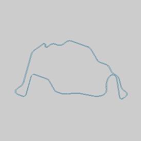
 Extract Edges.
 -
In the graphics area, to zoom-in, roll the middle mouse button.
Zoom-in until you can easily view the bottom surface of the part.
(If you don't have middle mouse button, give the graphics area focus, and use + and - on your keyboard to zoom in and out.) -
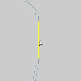
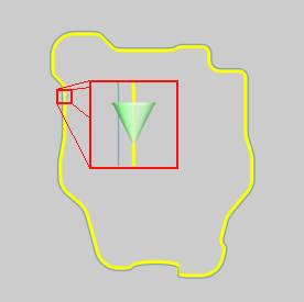
Select the bottom faces of the part as shown next.
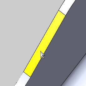
Continue to select these surfaces for theentire bottom of the part.
(To pan the view while selecting geometry,press and hold Ctrl and clickthe middle mouse button, then drag in any direction to move the part.Alternatively, in the document toolbar,click ![]() Pan.)
Pan.)
Be sure that you select the faces shown andnot the edges.Also make sure that you have selected all of the facesaround the bottom perimeter of the part.
-
To confirm the selections, click
 .(Alternatively,you can click OK in the Data Entry Manager.)
 -
Inthe DataEntryManager,click Cancel.
-
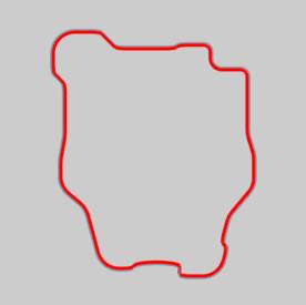
Inthe Layers tab, right-clickPart Model, and clickHide.
The extractededges on the Wireframe layer are now visible.
(If for any reason the lines created fromextracting the edges are not continuous, repeat the (Extract Edges) stepsand select only the surfaces that were missed.Be sure to create the geometryon the Wireframe layer.)
Part 3) Move Orientation Lines to a New Layer
-
Create a new layer and name it OrientationLines.
-
To enable selection mode, in the document toolbar, click
 .
. -
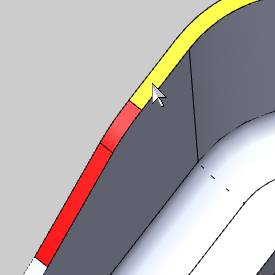
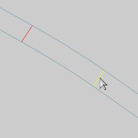
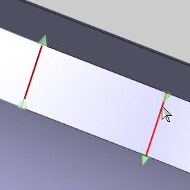
Zoom-in the view to select the lines thatconnect the inner and outer edge curves.Select all of these connectinglines.
-
After selecting the lines, right-click anywherein the graphics area, point toModifyAttributes,and click Color.
In the Colordialog box, select any color that is not the same as the current geometrycolor.
Now that you have changed the color, it iseasier to see if you have missed any orientation lines.
-
In the Quick Selection group, of the Home ribbon, click the down arrow next to
 Pick By Layer, and select
  Pick By Color.(SelectionMode must still be active.)
In the SelectColor dialog box, click the color of the orientation lines, andclick OK.
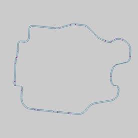
All of the lines are now selected.
-
Right-click in the graphics area,point to Modify Attributes,and click Layer.
In the SelectLayerdialog box, click Orientation Lines,and click OK. -
In the Layerstab, hide the Orientation Lineslayer.
The orientation lines are used later to definethe tool orientation.
This process also provides the ability tochain select the remaining curves, one of which is used later for thedrive curve selection.
Part 4) Add the Feature
-
In the Data-CAMTree Manager, click the CAM Tree tab.
-
Right-click
 MachineSetup and click Mill Multiaxis.
 -
In the MultiaxisWizard, confirm Wireframeis selected.
-
Click Next>>to go to the Posting settings.
Part 5) Define the Posting Parameters
-
The Work Offset # is automatically set tothe value defined in the Machine Setup.
You can change the value here to update theWork Offset # for the feature.
-
Click Next>> togo to the Multiaxis Posting settings.
Part 6) Define the Multiaxis Posting Parameters
-
Notice, at the top of the dialog box, that the Use Machine Settings checkbox is selected.
This means that the Multiaxis Posting parametersfor the feature use the same parameters as the machine that is selectedin Current Settings.
You can clear the UseMachine Settings check box to define the Multiaxis Posting parametersof the feature separately from the current machine settings.
An example usage is explained later.
-
Click Next>> togo to the Tool settings.
Part 7) Define the Tool Parameters
-
In the ToolData group, set the Diameterto 0.375 and the CornerRadius to 0.00.
-
Notice that the tool data is updated usinga tool from the Tool Library (using System Tool).
-
Click Next>>to go to the Parameters.
Part 8) Select Geometry
-
On the SurfacePaths tab, in the Edit Curvesgroup, click Drive Curves.
(The Orientation Lines layer mustremain hidden.) -
In the graphics area, hold down Shiftand select the inner-surface edge that you extracted to the Wireframelayer.
-
To confirm the selection, click
. -
In the EditCurves group, click OrientationLines.
Right-click anywhere in the Layers Manager, and click Hide All.
Right-click the OrientationLines layer, and click Show.
(You may need to zoom-in to see the lines,remember that they are very short in length.)
In the Selection group, of the Home ribbon, click ![]() Select All.
Select All.
This selects all of the currently visiblegeometry.
-
To confirm the selection, click
.
Part 9) Set the Direction of the Orientation Lines
You must confirm that all of the OrientationLines share the same chain direction.For this example, the chaindirection of all Orientation Lines must point towards the outside of thepart.If they do not share the same direction, an error message displayswhen you compute the toolpath.
-
To view the chain direction, first clickFinish to close the wizard.
Tip: In thispart of the tutorial, you must set the chain direction for the Orientationlines.To make it easier to set the direction, show the Part Model layerand rotate the view in the graphics area so that the bottom of the part isshowing (or press Ctrl+4).When you zoom in and out to check the chaindirection, this makes it easier to see if each line is pointing in theappropriate direction.Hide the Part Model layer again after completingthis part.
Make sure that the Orientation Lines andPart Model layers are visible.
-
In the CAM Tree, right-click OrientationLines, and click Modify StartPoint.
(You may need to expand the Geometry folder under the
 Multiaxisoperation.)
 -
The chain directionofeach orientation line is now visible.
Because the orientation lines are open chains, a start point and anend point indicate the chain direction. -
To change the chain direction, click the entity near the endto which the chain direction should point.
This task is most easily accomplished byfirst zooming-in until the chain direction is easy to view.After zoomingin, use panning to follow along the bottom of the part as you set thechain direction of each line.
Tip: When settingthe chain direction (using Modify Start Point), you do not have to clickthe entity directly.You can also click in the graphics area in the directionthat you want the chain direction to point.When using this method, clickin close proximity to the entity you are modifying.Use whatever methodyou find to work the best for you.
-
Continue this process until the direction of all orientationlines points to the outside of the part.
To confirm the selections, click ![]() .
.
Important: Asshown in this example, the chain direction of the Orientation Lines isset to start at the tool tip and point back towards the spindle.The chaindirection does not point towardsthe tool tip.
Whencomputing the toolpath, if a message displays about antiparallel lines,then the Orientation Lines are not all pointing in the same direction.Repeat Modify Start Point and correct the backwards chain direction.
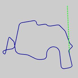
Part 10) Set the Direction of the Drive Curve
-
Before moving on, the chain direction ofthe drive curve must also be set.
For this example, our reference for the direction(clockwise or counterclockwise) is the top view.
Press Ctrl+1to select the top view of the part.(The Part Model layer must be hiddenand the Wireframe layer must be visible.)
In the CAMTree, right-click Drive Curves,and click Modify Start Point.
-
Zoom-in to view the start point and note the direction.
-
Regardless of the current chain direction, click
to exit Modify Start Point. -
If the chain direction was clockwise, right-click DriveCurves, and click ReverseDirection.
If the chain direction was already counterclockwise,no change is needed.
From the top view, the chain direction appearsas follows.
Part 11) Define the Parameters
-
To edit the feature, right-click
 FeatureMultiaxis, and click Edit.
Click Parameterson the left side of the dialog box.
In the Pattern group, the MaximumSnap Distance defines what Orientation Lines are included in thetoolpath calculation.This distance is measured from the selected DriveCurve.
For this example, because the orientationlines touch the drive curve, the default value of 0.100is used.
-
For this example, because the drive curve chain direction iscounterclockwise, set the MachiningSide to Right.
-
In the Sorting group,next to Direction for One Way Machining,select Follow Curve Chaining.
-
To create the toolpath, click Compute.
-
The program is not yet ready to simulate as the tool is currentlycutting with the tip of the tool pointing to the surface edge fromunderneath the part.(With the current tool orientation, the featurecould not be run on the machine as set up for this example.)
This is not the same orientation as the selected(orientation line) geometry.

Important: Inorder to have the tool orientation follow same orientation of the selectedOrientation Lines, you must set the Tilt Away from Line angle value to0.000 degrees.
Part 12) Define the Side-Tilt Angle
-
Edit the feature, and click Parameters.
-
Click the ToolAxis Control tab.
Notice the tilting strategy, next to Tool Axis Will, is set to Tilted Relativeto Cutting Direction. -
In the TiltAway from Line box, type 0.000.
-
Click Compute.
The toolpath is now offset to the bottomside of the part.
The tool orientation is now properly alignedwith the selected orientation lines.

-
Be sure to show the Part Model layer before simulating, or noworkpiece geometry is passed to simulation.
-
To view the program, in the quick access toolbar, of the CAM Tree Manager, click
 .
.
During simulation, the tool orientation isnow the same as the orientation lines.

-
To close simulation, click
 Exit Simulation.
For more help using simulation, view GettingStarted with Simulation.
Adjust the Machine Table Rotation
When you simulate the program, the machine table is sometimes rotatedin a way that doesn't allow you to view the part without rotating theview of the machine.You can change the Angle Pair settings for the featureto modify the table rotation used in simulation and in the posted code.
-
To edit the feature, in the CAMTree, right click
FeatureMultiaxis,and click Edit. -
Click theMultiaxis Posting icon in the tree.
-
Clear the UseMachine Settings check box.
-
In the AnglePair group, next to Use,select Other Solution.
When you simulate the program again, youcan now view the part being cut from the opposite side of the machine.
The table is rotated to use the other solutionto the rotation angles of the primary and secondary rotary axes (anglepair).This changes the posted output of the program as well as the simulation.
Tip: You don'thave to compute the toolpath to update this setting for simulation, butyou must Post the program to update the code if has already been posted.
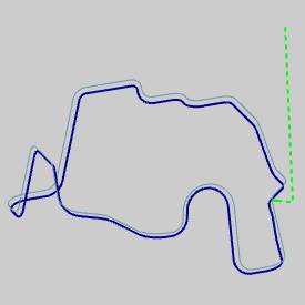
Part 13) Axial Shift
If you want to force the tool past the drive curve in order to cut usingmore of the flute, or a different part of the flute, you can use the AxialShift parameters.
-
Edit the feature, click Parameters,and click the Utility tab.
-
In the AxialShift group, notice the option Constantfor Each Contour.
This shifts the tool by the specified amount for the entire toolpath. -
In the Tobox, type -0.250.
(Negative values cause the tool to in-feed, and positive values retractthe tool.) -
To add the changes, clickCompute.
The result is visible in the toolpath display.(The toolpath moves towards the inside of the part.)
The following images show the tool positionbefore and after adding the Axial Shift.


This concludes the tutorial.