


How to Handle Custom Part Orientations
Introduction
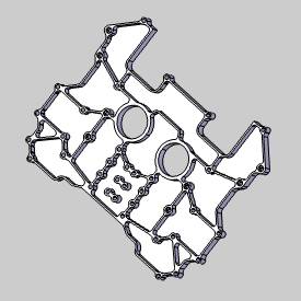
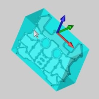
In this example, you learn how to use the stock orientation optionsto create stock for a part that is oriented in an arbitrary location inthe graphics area.The part model is shown first.This example will also provide links to related topics.
Example
In the Stock
-
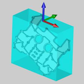
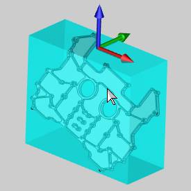
To begin aligning the stock to the part,in the Stock Orientation group,click X Direction, and selectthe desired X-axis direction from the part geometry as shown next.
The X-axis of the stock coordinate is aligned to the selected surfaceedge.
Further refine the direction of the axis with the Reverse button as needed. -
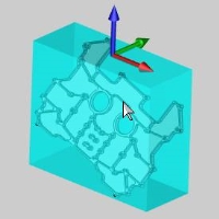
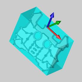
To further align the stock to the part, clickY Direction, and select thedesired Y-axis direction from the part geometry as follows.

The Y-axis of the stock coordinate system is now aligned to the selectedsurface edge.
Further refine the direction of the axis with the Reverse button as needed.

Tip: When settingthe X- or Y-Direction, you are not limited to using the part geometry.You can use any geometry that exists in the graphics area.
Tip: The ![]() (reverse) buttons be used to flip the orientations of any axis as needed.
(reverse) buttons be used to flip the orientations of any axis as needed.
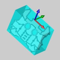
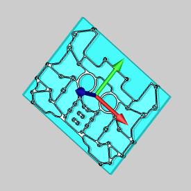
The stock is now aligned with the part, and thestock coordinate system is at the top and center of the stock.
Now that the stock orientation is aligned to thepart, you can add an offset to the stock.When you add an offset for customstock orientations, the axis directions are based off of the stock coordinatesystem and not the WCS.
This concludes the example.