


How to Create a Toolpath Pattern - Points
Introduction
This tutorial explains how to create a toolpath pattern using the Pointsoption.The example provided shows how to pattern multiple features togetherusing a single toolpath pattern with a Group.
Example Part
If you are connected to the Internet, the part file for this example can be downloaded automatically by clicking the following link: Toolpath PatternPoints Example 1.bbcd
Once you download and saved the zip file, extract the files on your system in an easy place to remember.You can then open the file to use with this tutorial.All files for the tutorials in this help system available for download can be found by clicking on the following link: http://www.bobcad.com/helpfiles.
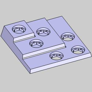
In the example file provided, the stock and MachineSetup are already defined for the part, the relevant toolpath has beenapplied, and a group has been created for the toolpaths being patterned.
Part 1) Blank/Unblank Toolpath
In this example part, we have used a Group to better manage our toolpaths.Adding a toolpath pattern to each of the three toolpaths we intend toduplicate would be a little too time consuming.Adding a toolpath patternto the entire machine setup, would duplicate toolpaths we have no intentionof patterning.The creation of a group, gives us control of all the toolpathscontained in the group at once.
-
In the
-
Right-click the Groupin the CAM Tree.
-
Select Blank/UnblankToolpath.
The toolpath for the three features we intend to pattern is no longervisible in the graphics area.
Part 2) Add the Pattern
With the toolpath hidden, we can now easily pick the points for ourpattern.
-
Right-click the Groupin the CAM Tree.
-
Select AddToolpath Pattern.
TheToolpath Pattern dialog appears. -
Select the Pointsoption.
-
Click Next> >.
Part 3) Set the Start for the Toolpath Pattern
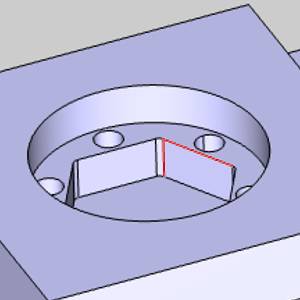
With the Toolpath Pattern dialog launched, we are now able to set theSpecified Points.If the distances between the original and its copiesare known, the Start can be left at zero and the differences can be entered.In this case we will use the Pick options to set the Start and usethe
Important: Pick optionsreference values in relation to the Machine Setup
-
Click the Pickbutton in the Start groupto set the start position.
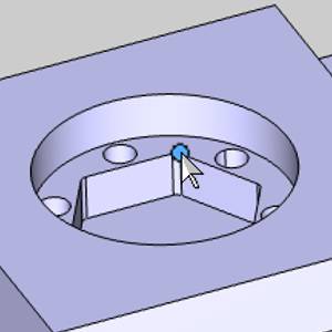
The Toolpath Pattern Dialog hides and selection mode is enabled. -
Click the
 OK.
OK.
The Toolpath Pattern dialog returns.
Part 4) Set the Positions
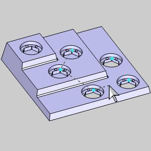
The Start and Positions determine the distances of our toolpath duplicatesfrom the originals.Since we have used the Pick option to select our Start,we will use the Pick Positions option to select our Positions.
-
Click PickPositions.
The Toolpath Pattern Dialog hides and selection mode is enabled. -
Take care to select the matching
-
Click OK.
The Toolpath Pattern dialog returns.
Part 5) Set the Machining Order
The last group in the lower right of the Toolpath Pattern dialog box,is Machining Order.This groupwill allow you to select from Optimized, or Pick Order.To have controlover the order our copies are machined in, we will need to set the MachiningOrder to Pick Order.
-
Click the PickOrder option in the Machining Order group.
-
Click OK.
The Toolpath Pattern dialog closes.
Thetoolpath will now be machined in the order the Positions were selected.
Part 6) Simulate the Program
-
To view the part being cut, right-click
 Milling Job,and click Simulation.
To learn more about using Simulation, viewGettingStarted with Simulation.
The resulting stock model is shown next.
-
To close the simulation, click
 Exit Simulation.
This concludes the tutorial.