


Creating Milling Tool Holders
Introduction
In this topic, you learn how to createa Tool Holder and Tool Arbor.You also learn the distinction between theTool Holder and Tool Arbor as it is defined for Bob
Tip: Whencreating tool holders, any changes that are made in the dialog box affectthe currently selected item.Make sure that you have the proper item selectedbefore making any changes.
Steps:
Part 1) How to Open the Milling Tool HolderLibrary
To access the Milling Tool Holder Library,do one of the following:
-
In the CAMtree, right-click
 CAM Defaults, and click Mill ToolHolders.
-
In the CAMtree, right-click
 Milling Tools, and click Mill ToolHolders.
(You can also click AssignTool Holder in the Milling Wizard Tool page to assign a holderto the tool for the operation.)
The Milling Tool Holder Library dialog boxappears with the default tool holders.On the left side, a Tool Holdercategory is selected, and all of the tool arbors for that category arelisted on the right.
Part 2) How to Add and Name a Tool Holder Category
-
To add a new ToolHolder Category, in the Holdersgroup, click Add Holder.
The Tool Holder Definition dialog box displays. -
To name the new holder, In the HolderDescription box, type My Holder1.
Part 3) How to Create a Tool Holder
-
To define the first element, in the Element List, click Cylinder.
In the ElementParameters list, type the following values.
|

|
-
To define the next element, in the ElementList group, click AddCylinder, and type the followingvalues.
|
|

Be sure to click the arrow next to TopChamfer, and then click Top Fillet.
-
Click Add Cone, andtype the following values.
|
|
-
Click Add Cone.
After adding this cone, you realize that a cylinderis needed before the cone.
Instead of deleting the cone, click AddCylinder.
To reorder the elements, click MoveUp.
With the cylinderselected, type the following values.
|
|
-
In the Element List,select the cone that was previouslyadded, and type the following values.
|
|
-
Click AddCylinder,and type the following values.
|
|
-
To finalize the new tool holder, click OK.
In the Milling Tool Holder Library, notice thatthe new Tool Holder Category (My Holder 1) displays on the left side.
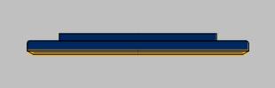
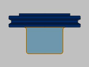
This now completes the process of making aTool Holder and category.The geometry only includes the portion of thetool holder that is exposed from the spindle down to the bottom of theV-flange.The rest of the tool holder, below the V-flange, is classifiedas the tool arbor.The tool arbor is created next.
Tip: Thecenter section (V-flange) of the tool holder uses multiple cylinders andcones.To create a chamfer that is not 45 degrees, you use a cone.Tocreate a 45 degree chamfer, you use a cylinder with the chamfer option.
Part 4) How to Create a Tool Arbor
The tool holder created in the previous part is a CAT 50 end-mill holder.Since there is already a CAT 50 tool holder category, there is no needfor My Holder 1.The next step is to eliminate this category in orderto add the new tool arbor in the default CAT 50 category.This keeps allCAT 50 tool holders/arbors together in one category.In addition, whenyou use Delete Holder,theentirecategory, including the holder and all arbors, is deleted.Whenyou use Delete Arbor, you are only deleting a single arbor.
-
To delete the unnecessary holder category,first make sure that My Holder 1category is selected, and in the Holdersgroup, click Delete Holder.
A message displays to confirm that you want to delete the selectedholder.
Make sure that My Holder 1is in this description, and click Yes. -
In the ToolHolder Category list, select CAT50 Holder.
To create an arbor within this category, in the Arborsgroup, click Add Arbor.
Notice that the Tool Holder Definitiondialog box displays the defined tool holder.
The first arbor element, in this case the default cylinder, startsat the bottom of the tool holder. -
To name the arbor, in the ArborDescription box, type 1.0inch I.D. x 3 Arbor CAT 50.
This description is the label used when you assign a tool holder/arborto a tool. -
Since the first element of the arbor is acylinder, in the Element Parametersgroup, type the following values.
|
|
-
In the Element List,click AddCone,and type the following values.
|
|
|||||||||||||
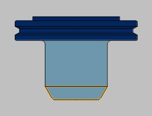
Tip: Thecylinder element (step 4) has a diameter of 1.97 with a bottom filletof 0.118.The cone element (step 5) has a diameter of 1.97 witha top fillet of 0.118.When two elements share the same diameter wherethey meet, you can apply a fillet across the two elements.To apply thefillet across the two elements, you must use the same fillet value foreach element (Top Fillet of one element and the Bottom fillet of the next).
-
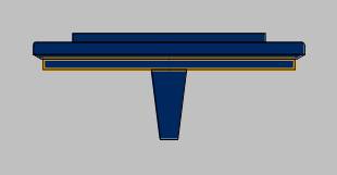
To finalize the new tool holder/arbor, click OK.
You have added a stubby CAT 50 tool arbor to theCAT 50 category.
How to Measure Angle Mode
|
Bottom Angle Mode = 45 degrees |
|
|

A Final Note on Creating Tool Holders
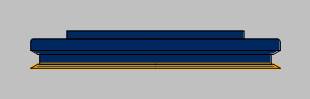
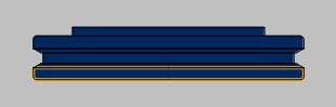
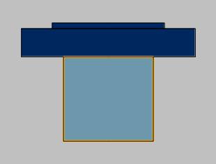
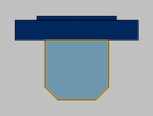
This tutorial is designed to show you how detailed you can be when creatingtool holders.Although you have the ability to create an accurate toolholder model, this may not be necessary.The more detailed the tool holderis, the longer the calculation times are for simulation.Keep this inmind when creating tool holders.If you want to keep the calculation timea short as possible, you can use very simplified tool holders as shownnext.
|
|
|
This concludes the tutorial.