


How to Create 2 Axis Inside Features
Introduction
In this tutorial, we examine how to create Wire EDM Inside features. Be sure to complete the Getting Started with Wire EDM Features tutorial to get important information about Wire EDM features that isn't included in this tutorial. This tutorial provides a 2 Axis Inside step-by-step example, with a focus on the leads, glue stop options, and feature start point. Most of the information contained in this tutorial can be applied to both 2 Axis and 4 Axis Wire EDM Features.
Example File
If you are connected to the Internet, the part file for this example can be downloaded automatically by clicking the following link: Wire EDM 2 Axis
Features Example 1.bbcd
Once you download and saved the zip file, extract the files on your system in an easy place to remember. You can then open the file to use with this tutorial. All files for the tutorials in this help system available for download can be found by clicking on the following link: http://www.bobcad.com/helpfiles.
In the example file provided, the stock and machine setup are already defined for the part.
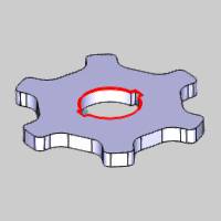
The part model, stock, and machine Setup for this tutorial are shown next.

Part 1) The Feature
Feature and Feature Geometry
-
In the CAM Tree, right-click Machine Setup, and click 2 Axis Inside.
The Wire 2 Axis Wizard displays. -
In the first page of the wizard, click Select Geometry to assign the feature geometry.
The Feature Geometry Picking dialog appears with focus on the Selected Geometry list by default. -
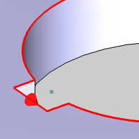
In the graphics area, right-click the inner surface edge of the model, and click Constant Z. (Wireframe geometry can also be selected)


The geometry is added to the Selected Geometry list.
Tip: For 2 Axis features, you select a single profile from the top or bottom of the part. The software automatically projects the selected profile to the bottom (and top) of the stock defined for the job (2 Axis features without taper). When applying taper to a 2 Axis feature, select the profile from any Z-height and use the Taper from Bottom option to apply the taper to the bottom or top of the feature.
Profiles Chains and Start Points
-
After selecting the profile, click in the Profile Chains list to give it focus.
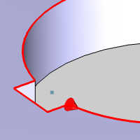
Notice the location of the Start Point. -
Above the Profile Chains list, in the Start Point group, select the check box for Closet to Points.
The Select Points list appears. -
Click in the Selected Points list to give it focus.
-
Select the point in the graphics area.
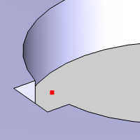
The point is added to the Selected Points list. -
Above the Selected Points list, click the Closest to Points button.
-
Click back in the Profile Chains list and notice the updated start location.
-
Click OK to return to the wizard.
Note: The start point location could have also been updated by clicking on the profile chain in the list and using your mouse in the graphics area. To learn more about selecting geometry, view the Wire EDM Wizard Geometry Selection.
Parameters
-
Click Next>> to go to the Feature settings.
For this example, we start with the defaults for all Feature settings. -
Click Next>> to go to the Machining Strategy.
-
In the Machining Strategy, the Default Strategy of 2 Axis Inside Strategy 1 is used.
The Current Operations list should show three operations: 2 Axis Rough Cut, 2 Axis Tab Cut, and 2 Axis Skim Cut. Notice that the Tab Cut operation comes before the Skim Cut operation. This is the default template for Inside feature types. This allows you to cut the rough shape with the Rough Cut operation, glue the core of the part before performing the Tab Cut operation, and then finish the entire inside profile using the Skim Cut operation. -
Click Next>> twice to go to the Posting settings.
(For information on the Wire settings, view the Wire EDM Wire Settings. -
Confirm that the proper Work Offset Number is selected for the feature.
For more information about the Posting page, view the Wire EDM Posting Settings. -
Click Next>>.
The Machine Sequence is only used when you select more than one profile for 2 Axis features, so we can skip the next page. To learn more, view the Wire EDM Machine Sequence. -
Click Next>> again to go to the Rough Cut operation Parameters.
Part 2) Rough Cut Operation Parameters
Applying Leads to all Operations
For this part of the example, we use the default settings for Parameters and Corner Types.
-
In the tree on the left side of the wizard, below 2 Axis Rough Cut, click Leads.
-
In the Lead-in group, set the Length value of the Perpendicular lead to 0.050.
This is not what we want for the Lead-in, but we are about to save ourselves a little time. -
At the bottom-left of the wizard, click Apply to All Operations.
While we did not want this Lead-in method for our rough, we did want it for every other operation. Now we just update our rough lead-in.
Updating the Rough Cut Lead-In
-
In the Lead-out group, click to clear the Same as Lead-in check box.
This allows us to update our Lead-in while leaving the Lead-out as is. -
In the Lead-in group, next to Type, click the down arrow, and click Select Point.
Notice that First Point X, First Point Y, and Pick Points become available in the Lead-in group.
Note: These buttons are labeled as First Point and Select Points because when you select more than one shape (profile) for a single 2 Axis feature, you can select a lead-in point for each profile. In this case the dialog box displays the values of the first point. For single profile features, you only select one point.
-
Click Pick Points.
The Pick Lead-in Points dialog appears. -
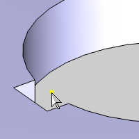
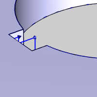
In the graphics area, select the point.


-
Click OK.
Notice that First Point X and First Point Y automatically update the values to the selected point. -
Click Next>> to go to the Cutting Conditions.
-
Notice that the Link to Database check box is selected by default. For this example, we use the values loaded from the current database.
Part 4) Tab Cut Operation Parameters
For this part of the tutorial, we use the default settings for Parameters, the leads we have already applied, and Link to Database for the Cutting Conditions.
-
In the tree on the left side of the wizard, under 2 Axis Tab Cut, click Leads.
-
Notice the leads have our length value already applied.
Had we set the length value here and used the Apply to All Operations option, we would have eliminated the Select Point Lead-in for our Rough cut. -
Click Next>> until you reach the 2 Axis Skim Cut operation Parameters.
Part 5) Skim Cut Operation Parameters
For this operation, we update our parameters to use reversed skims, use the default settings for Corner Types, the leads we have already applied, and Link to Database for the Cutting Conditions.
-
In the Skims group, select Reverse Skims.
This means that each Skim Cut pass alternates cutting direction along the profile (and the first Skim Cut pass is opposite the direction of the previous operations.) -
In the Number of Skim Passes box, type 2.
-
Click Leads under 2 Axis Skim Cut.
-
Notice these leads also have the desired length applied already.
-
To create the wirepath for the feature, at the bottom of the wizard, click Compute.
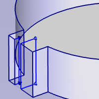
Tip: To make the wirepath easier to view, the part is made transparent (press T or click View, Transparent), and the Rough Cut operation is selected in the CAM Tree to highlight the operation.
Part 6) Reviewing Wirepath
After finishing the wizard, the feature is added to the CAM Tree. You use the Wire EDM Feature in the CAM Tree to modify the feature from this point. After creating the feature, do a visual inspection of the wirepath to ensure it looks as expected. In this part we hide the wirepath of all operations so we can inspect each operation individually.
Selecting the Auto Blank New Items option automatically eliminates the in the CAM page of the System tab in the Current.
-
In the right-click our EDM 2X Inside feature and select Blank/Unblank Toolpath to hide the toolpath.
-
In the CAM Tree under
 Feature EDM 2X Inside, click 2 Axis Rough to view the toolpath for this operation.
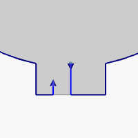
Notice the path starts from our specified point and leads perpendicularly into our chain start point, and then leads out of the profile before completing the pass to create the glue stop. -
In the CAM Tree under
Feature EDM 2X Inside, click 2 Axis Tab Cut to view the toolpath for this operation.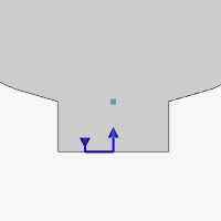
Notice the path starts from the lead-out position of our previous operation and cuts the tab left by the glue stop. -
In the CAM Tree under
Feature EDM 2X Inside, click 2 Axis Skim Cut to view the toolpath for this operation.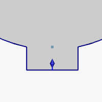
Notice the path starts from the lead-out position of our previous operation and skims the entire shape.
Part 7) Use Glue Stop Without Leads
For Inside features and Open features set to Die, the Glue Stop Option, Glue Stop without Leads, can be applied to remove the lead-out of the previous operation and the lead-in of the Tab Cut operation so the feature stops directly on the profile before performing the Tab Cut operation.
-
To edit the feature, right-click Feature EDM 2X Inside, and click Edit.
-
Under Glue Stop Options, click the down arrow, and click Use Glue Stop without Leads.
-
To update the feature, click Compute.
-
In the CAM Tree under
Feature EDM 2X Inside, click 2 Axis Rough to view the toolpath for this operation.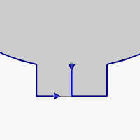
Notice the path starts from our specified point and leads perpendicularly into our chain start point as it did, but now has no lead out when stopping to create the glue stop.
This option is only available for Inside features and Open features set to Die, and it helps to reduce the cycle time for the feature. -
In the CAM Tree under
Feature EDM 2X Inside, click 2 Axis Tab Cut to view the toolpath for this operation.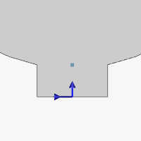
Notice the tab cut also updates to start from the updated position of our previous operation and still cuts the tab left by the glue stop.
This completes the tutorial.