


How to Use The Syncing Options for 4 Axis Wire EDM Features
Introduction
This example explains how to use the Syncing Options for 4 Axis Wire EDM features. The syncing options determine how wire is aligned between the upper and lower profiles of the feature. BobCAD-CAM offers three unique syncing options in addition to the ability to select Sync Line geometry for situations in which you want even more control.
Navigation
The Syncing Options display on the Feature page of the Wire 4 Axis Wizard. When needed, sync line geometry can be assigned using either the Geometry Selection page of the wizard or using the Geometry item of the feature in the CAM Tree.
Syncing Options
By Entity
The By Entity syncing option is ideal for features in which the upper profile and lower profile contain an equal number of entities.
The following images show the result of using By Entity with a feature that contains an equal number of entities in the upper profile and lower profile.
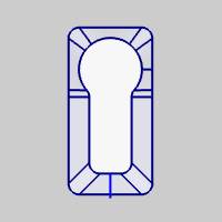
By Proportion
The By Proportion syncing option is ideal when you do not have an equal number of entities in the upper profile and lower profile (or when one of them is a single entity).
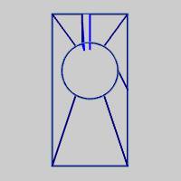
The following images show the result of using By Proportion with a feature that contains a single entity (an arc) in the upper profile and four entities in the lower profile.
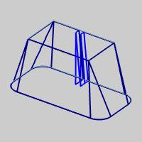
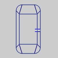
By Closest
The By Closest syncing option is ideal when you want the upper profile and lower profile to sync to the closest start or end point of the opposite profile.
The following images show the result of using By Closest with a feature that contains four entities (rectangle) in the upper profile and eight entities (rectangle with corner radii) in the lower profile.
Sync Lines
In addition to the syncing options, you can also select sync lines directly from the graphics area using either lines or surface edges. You can select one or more sync lines until the entire feature is synced as desired. Your sync line geometry should be connected to both the upper profile and the lower profile and you must compute the feature to update any changes after modifying your selections.
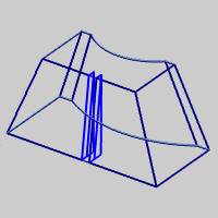
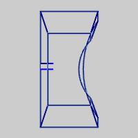
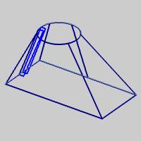
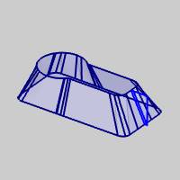
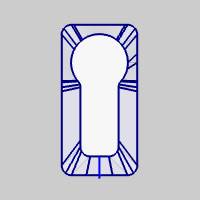
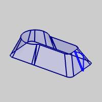
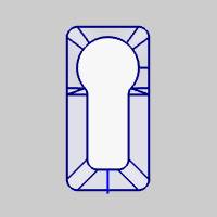
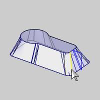
The following images show all three syncing options applied to a solid model without selecting sync lines.
By Entity
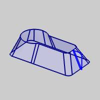
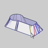
By Proportion
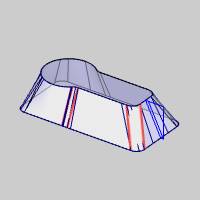
By Closest
Selecting Sync Lines
While the Syncing Options should handle most situations without the need to select sync line geometry, there may be some features in which you need more control.
The following example shows By Proportion applied to the solid model as shown earlier. While this syncing result may be acceptable for this feature, we pretend that this is not our desired result (and that By Entity can't be used).
You can then select sync lines directly from the model (or lines can be drawn between the upper and lower profile when using wireframe geometry) as shown next.
After confirming the sync line selection and computing the wirepath, the following results. (You can see that the syncing starts to resemble the result created By Entity.)
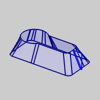
Notice that the wirepath is only changed in the area of the selected sync lines, and the rest of the path remains the same.
Tip: You can select any amount of sync lines for a feature as needed. If you are having problems with syncing in a certain part of a feature, you can select sync lines in the problem area only. In this case you may want to select one sync line at a time and compute the feature to view the changes. This way you don't select any sync lines that aren't actually needed.