 Align to Coordinate System
Introduction
This topic will explain the Align to Coordinate System function, the options found in it, will describe where to find the function, provide quick steps on how to use it, and provide links to related topics.
The Align to Coordinate System function
The Align to Coordinate System function is used to simultaneously move and rotate geometry.
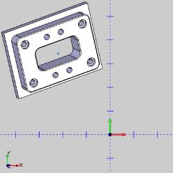
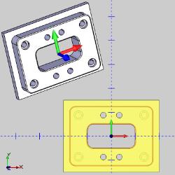
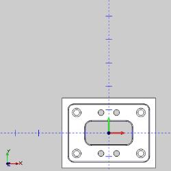
There are times BobCAD-CAM users open customer parts to find them oddly placed and oriented in relation to the World Coordinate System. This can be due to a variety of reasons, and while it is not necessary to move it at all, users that want to will find it easy enough to translate geometry. The tricky part can be figuring out the proper rotation. The Align to Coordinate System option make it easy to move, and rotate any geometry quickly and accurately.
Navigation
To open Align to Coordinate System:
- In the Move group, of the Utilities ribbon, click
 Align.
The parameters display in the Data Entry Manager.
The Data Entry Parameters
- Preview
 - With this check box selected a preview of the part will show where the selected geometry will be positioned if the function is completed.
 - With this check box cleared, a preview will not be visible.
 Geometry
The Geometry section determines how geometry is selected for the function. You can automatically use everything currently visible, or pick geometry manually.
-
 All visible - With this option selected, any geometry that is unblanked, on any layer that is shown will automatically be selected for the function.
 -
 Pick - With this option selected, only geometry that is manually selected will be used in the function.
 From
From
The From section determines where the selected geometry is being moved from, both in position and orientation.
-
 Coordinate System - With this option selected, any geometry that is unblanked, on any layer that is shown will automatically be selected for the function.
 -
 Existing UCS - With this option selected, only geometry that is manually selected will be used in the function.
With the Coordinate System option selected, the following parameters are available:
Coordinate System
Origin - is used to select geometry in the graphics area as the origin.
|
|
|
| This list box will show the entity currently selected for the function. | |
-
X - determines the change in distance along the X-axis of the WCS.
-
Y - determines the change in distance along the Y-axis of the WCS.
-
Z - determines the change in distance along the Z-axis of the WCS.
X Direction - this allows you to select geometry that defines the direction for the X Axis. The last geometry selected will show in the list.
|
|
|
| This list box will show the entity currently selected for the function. | |
Y Direction - this allows you to select geometry that defines the direction for the Y Axis. The last geometry selected will show in the list.
|
|
|
| This list box will show the entity currently selected for the function. | |
Z Direction - this allows you to select geometry that defines the direction for the Z Axis. The last geometry selected will show in the list.
|
|
|
| This list box will show the entity currently selected for the function. | |
Important: When geometry is selected to orient a particular axis, that geometry is saved in the list. If new geometry is selected for another axis that conflicts with the geometry assigned for another axis, the geometry selected last will take precedence.
With the Existing UCS option selected, the following parameters are available:
Pick From Existing UCS
-
This list will allow you to select an existing UCS to assign as the initial position and orientation for the selected geometry.
 To
To
The To section determines the final position of the selected geometry, both in position and orientation.
-
 Coordinate System - With this option selected, any geometry that is unblanked, on any layer that is shown will automatically be selected for the function.
 -
 Existing UCS - With this option selected, only geometry that is manually selected will be used in the function.
With the Coordinate System option selected, the following parameters are available:
Coordinate System
Origin - is used to select geometry in the graphics area as the origin.
|
|
|
| This list box will show the entity currently selected for the function. | |
-
X - determines the change in distance along the X-axis of the WCS.
-
Y - determines the change in distance along the Y-axis of the WCS.
-
Z - determines the change in distance along the Z-axis of the WCS.
X Direction - this allows you to select geometry that defines the direction for the X Axis. The last geometry selected will show in the list.
|
|
|
| This list box will show the entity currently selected for the function. | |
Y Direction - this allows you to select geometry that defines the direction for the Y Axis. The last geometry selected will show in the list.
|
|
|
| This list box will show the entity currently selected for the function. | |
Z Direction - this allows you to select geometry that defines the direction for the Z Axis. The last geometry selected will show in the list.
|
|
|
| This list box will show the entity currently selected for the function. | |
Important: When geometry is selected to orient a particular axis, that geometry is saved in the list. If new geometry is selected for another axis that conflicts with the geometry assigned for another axis, the geometry selected last will take precedence.
With the Existing UCS option selected, the following parameters are available:
Pick From Existing UCS
- This list will allow you to select an existing UCS to assign as the final position and orientation for the selected geometry.
- OK - finalizes the function.
- Cancel - exits the function.
Quick Steps - Align
Step 1: Open the function and select geometry
- Open the function, and leave the Preview check box selected.
- By default, the All visible option is selected in the Geometry section. This option automatically selects all visible geometry for the function. If more or less geometry is necessary, either:
- Leave the All visible option selected, and adjust the amount of visible objects.
- Select the Pick option.
The Selected Geometry list becomes available to allow you to select geometry manually.
- Leave the All visible option selected, and adjust the amount of visible objects.
Step 2: Choose where the geometry is being moved from
- Choose where the geometry is being moved from by either:
- By default, the Coordinate System option is selected for the From section. With this option selected:
- Click in the Origin list box and choose a point, or snap point.
The point is added to the list, the X, Y, and Z values are updated and focus is given to the X Direction list. - Choose a line or edge to define what the X Direction should be parallel to.
The Point is added to the X Direction list, the X direction of a gnomon appears, and the Y Direction list is given focus. - Choose a line or edge to define what the Y Direction should be parallel to.
The Point is added to the Y Direction list, the rest of the gnomon appears, and the Z Direction list is given focus. - Use the Reverse buttons found next to the direction lists to update the direction of the coordinate system as necessary.
- Click in the Origin list box and choose a point, or snap point.
- Choose the Existing UCS option and select a previously defined UCS.
- By default, the Coordinate System option is selected for the From section. With this option selected:
Step 3: Choose where the geometry is being moved to
- Repeat the exact steps from the previous section to define where the geometry is being moved to.
Step 4: Finalize the function
- With the preview in the desired position, click OK.
The geometry is moved.
Note: When this feature is applied to solids, or surfaces, a CAD feature is added to the CAD Tree.
Tip: Instead of applying features to solids and surfaces more than once, go to the CAD Tree to edit the existing feature. Since all solid and surface moves, and modifications are stored in the CAD Tree, editing a feature is preferable to adding many more to achieve the desired result. This will keep file size down and help ensure files don't become slow to respond.
- Click Cancel to close the function.
Example
In this example, we have a part that has odd orientation and placement on import. The goal is to place the part center at the center of the world coordinate system, and correct its orientation at the same time.
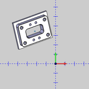
- In the Move group, of the Utilities ribbon, click
 Align.
The function opens in the Data Entry Manager. - By default the Geometry option is set to All visible, and the From group is set to Coordinate System with focus on the Origin list box. This allows you to set up a coordinate system on, and aligned with the part, that we can use to move and orient the part as we would like.
In the graphics area, click the point at the center of the part.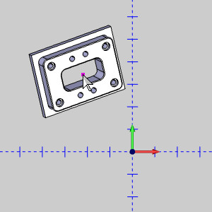
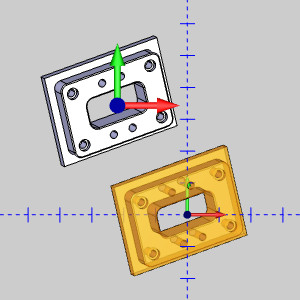
A coordinate system appears at the selected Origin, and we can see a preview of how our part will be placed with the settings as they are now.
The X Direction list box is automatically given focus. - Hover over the bottom edge of the part and notice the snap points that appear.
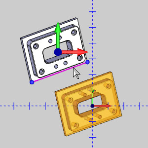
Click the snap point to the right.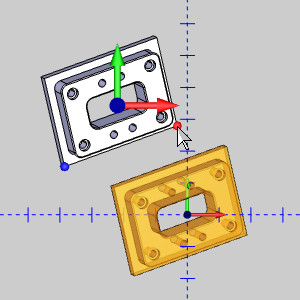
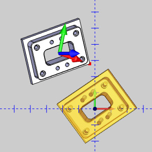
The point is added to the X Direction list box, and focus is moved to the Y Direction list box.
Notice how our X Axis is pointing directly at the snap point. When a point is selected the axis points at it. When an edge or line is selected, the axis will be parallel to it.
Lets update our X Direction. - Click in the X Direction list box to give it focus again.
- Hover the bottom edge of the part and click it to update the X Direction.
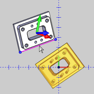
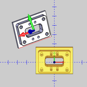
The X Direction is updated and focus is placed back on the Y Direction. - Hover over the left edge of the part to highlight it, then click the edge.
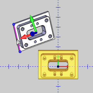
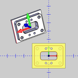
The Y Direction is updated, and the Z Direction list box is given focus.
In the case of the Z Direction, we only need it to flip direction. Because of this, we do not need to select geometry to associate it with. - Next to the Z Direction list box, click
 Reverse Direction.
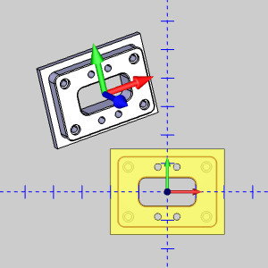
The Z Direction flips. - By default the To group is set to use an Existing UCS, with the Top (X/Y) UCS selected. In this case, this is what we want.
Click OK.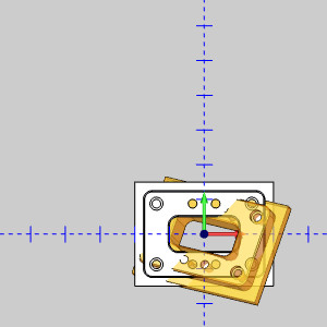
The part is moved and the preview updates to show how the part location and orientation will be updated if you were to click OK again. - Click Cancel to exit the function.
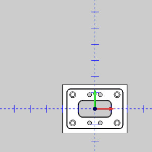
This conclude the example.


