The Advanced UI Surface Paths Tab : Advanced Planar
Introduction
This topic explains the Surface Paths tabs of the Advanced UI in the Advanced Planar operation, and provides links to the related topics.
The Surface paths tab
The Surface Paths tab of the Advanced UI contains many of the parameters
used to define the feature toolpath.
Parameters
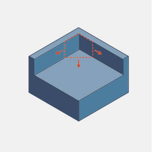
Machining direction
- Top - leaved the toolpath plane parallel to the X/Y axis.
- Other direction - allows you to define the toolpath plane vector by entering its X, Y, and Z, values, or by using the Select tool plane button to pick a line whose vector the normal of the toolpath plane should be aligned with.
Pattern
-
High speed - this pattern provides fast corner and fillet processing, but eliminates several other options, including the Machining surfaces, and DHC dialogs.
Machining surfaces
New surface
Use the Machining and Fixture buttons to add items to the list.
- Machining..
- adds another surface to the list.
- Fixture.. - when using the Advanced Rough, this option becomes available, and adds another fixture to the list.
- Delete - removes selected geometry from the list.
- Machining surface
- When a machining surface is highlighted in the list, clicking the ellipses button enables selection mode for you to assign geometry to the highlighted item.
- Fixture surface
- When a fixture surface is highlighted in the list, clicking the ellipses button enables selection mode for you to assign geometry to the highlighted item.
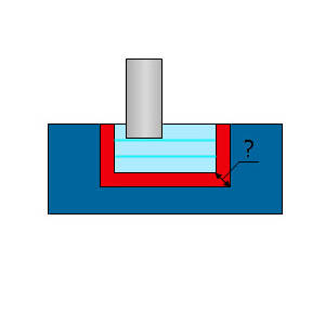
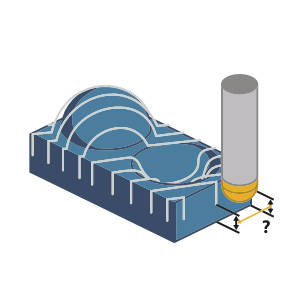
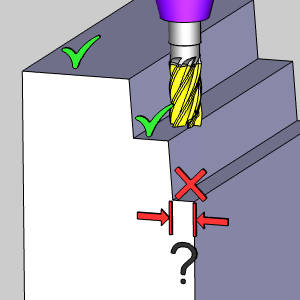
- Offset type - This parameter determines the amount of material or stock that is allowed to remain on the drive surface after an operation.
 Global - expands the machining faces in all directions.
- Radial and axial
- Radial offset - expands the machining faces in the X/Y direction.
- Axial Offset - expands the machining faces in the tool axis direction.
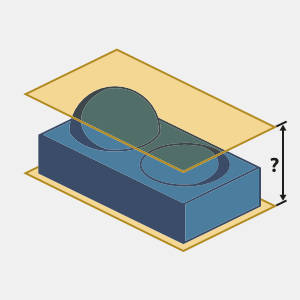
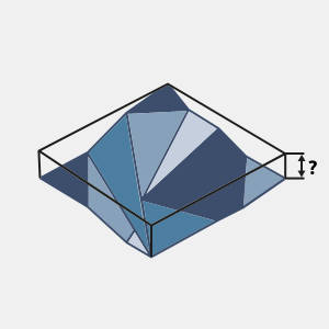
- Heights...
- Click Heights... to open the Heights dialog. The heights define the height area to be machined. Typically you can set the heights manually by entering 2 values, the start and end height. This height will be measured along the machining direction. Another possibility is to use the 'Automatic heights' which will basically create a bounding height around the selected drive surfaces.
Dynamic holder collision avoidance
Clearances
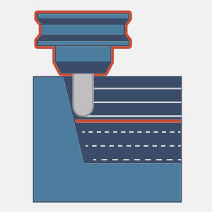
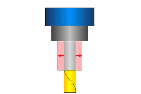
- Shaft - allows you to define the clearance used for the shaft of the tool.
|
|
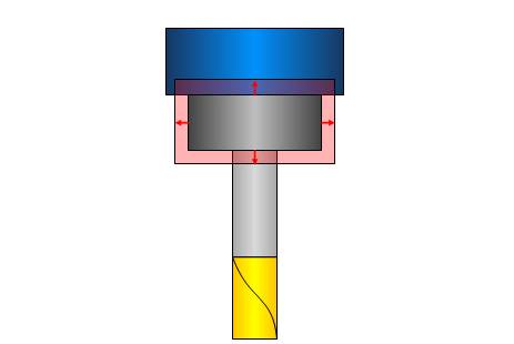
- Arbor - allows you to define the clearance used for the arbor of the tool.
|
|
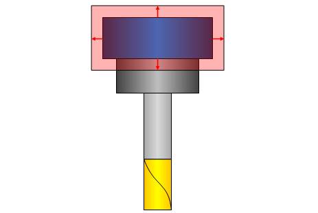
- Holder - allows you to define the clearance used for the holder of the tool.
|
|
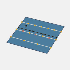
- Machining angle in X,Y - defines the toolpath angle in the XY plane.
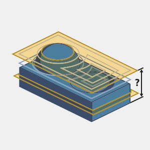
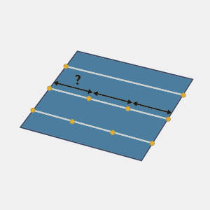
- Multiple passes on full width cut - creates additional cuts in the vertical plane when the depth between the current and previous cuts is more than Step over value.
- Depth step - determines the spacing between vertical cuts when using Multiple passes on full width cut.
- Optimal machining angle in X,Y - allows you to have the system calculate the machining angle to use based on the geometry selected. This option is only available when using the High speed option, and disables the manual machining angle in X,Y value input option.
Area
Undercuts machining
-
Type - is set to 3+2 and enables detection and processing of undercut areas in the specified range.
-
Maximum tilt angle - defines the maximum amount of tilt allowed in the search.
-
Minimum undercut depth - defines the depth at which an undercut will be considered for machining.
-
Process both directions - allows for the processing of opposite machining directions.
-
Check surfaces - opens geometry selection for check surfaces to be chosen.
-
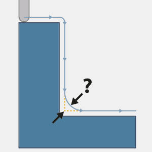
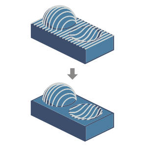
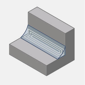
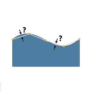
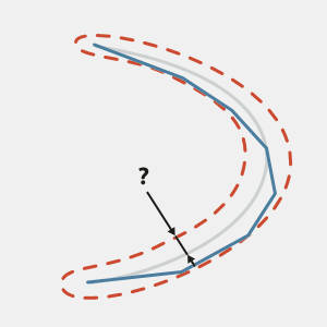
Round corners - smooths cutting segments based on the maximum deviation used in the dialog, as seen in the image below.
-
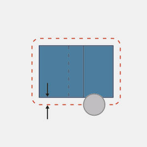
 2d Containment - contain the toolpath within a selected curve.
2d Containment
Trimming criteria
- Tool tip point - defines the boundary in relation to the tip of the tool.
- Tool contact point - defines the boundary in relation to the point of contact between the tool and the machining surface.
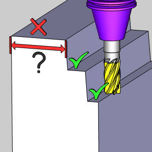
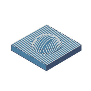
Exclude flat areas
-
Flat Tolerance Factor - This can aid in recognizing flats in models with poor mesh quality. While this value can normally be left at the default value, increasing it will loosen the definition of what is considered a flat area in the mesh, which can result in toolpath being applied to areas previously not considered flat.
-
Minimum Width - Areas under this width will have toolpath applied, thereby ignoring the Exclude Flat Areas feature.
-
Maximum Width - Areas over this width will have toolpath applied, thereby ignoring the Exclude Flat Areas feature.

- No maximum width is set, and the Minimum Width and Tolerance will control the areas the feature is applied to.
- A maximum width is set to work along with the Minimum Width and Tolerance to control the areas the feature is applied to.
-
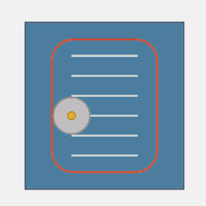
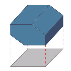
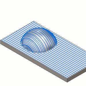
Silhouette containment - limits the machining area by the silhouette of the machining surfaces projected along the machining direction. This applies to the Advanced Planar, Advanced Z Level Finish, Equidistant, and Advanced Rough operations.
Silhouette containment
Defined by
-
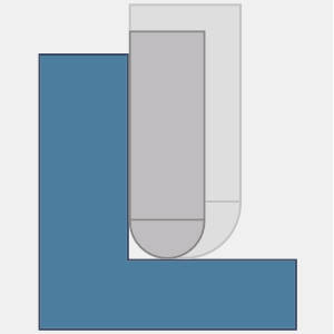
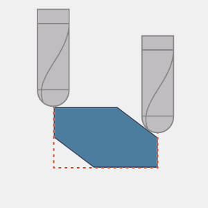
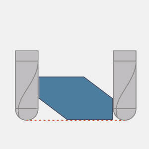
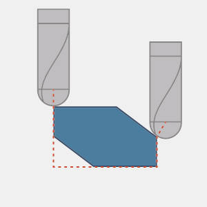
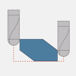
Part silhouette - is the default setting. The machined area is limited to the tool center line which follows the actual part silhouette. The tool does not reach beneath the containment. For shallow areas the tool does not reach the outer edge.
-
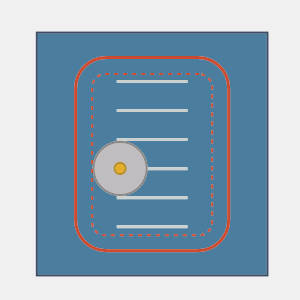
Part end height - is offset outwards by the tool radius to get to full depth.
-
Tool contact - adjusts the boundary as needed so the contact point between the tool and machining surface is what stops at the boundary.
-
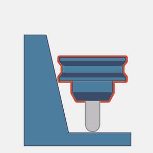
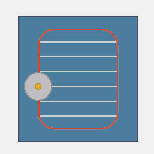
Top of vertical walls - stops the machining at the top of vertical walls.
-
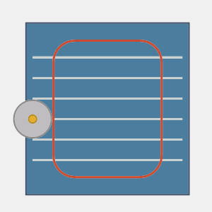
Bottom of vertical walls - stops at the bottom of the vertical walls.
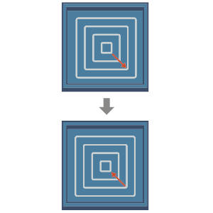
Sorting
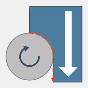
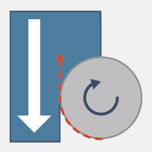
- Reverse cutting order
Select the check box to swap the cutting order, from inside to outside, to outside to inside.
Clear the check box to retain the original cutting order.
- Cutting method - controls the cutting method or the toolpath pattern. Select either:
- Zigzag - the tool alternates the cutting direction with every new cut. This means the cut starts at one side and then moves to the other side. Once it reaches the other side, the tool cuts back in the opposite direction. The cuts are joined by the parameters set up in the Links page.
- One Way - the tool cuts in one direction. This means that each cut starts on one side and ends on the opposite side. The cuts are joined by the parameters set up in the Links page.
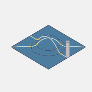
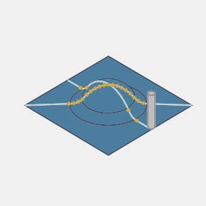
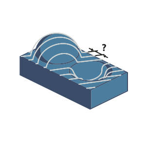
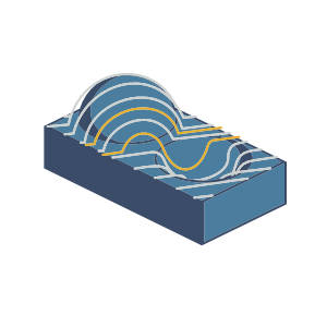
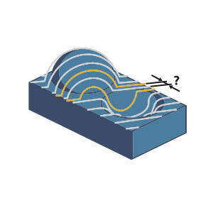
- Up / Down - is designed for tools which can only machine in an upward/downward direction. This toolpath moves along the defined machining angle, but moves lifts up and moves to locations to reengage in a manner which will continue to engage material in an upward (or downward) manner as seen in the animation below.
- Advanced - launches the Advanced options for up and down machining. Which gives you access to:
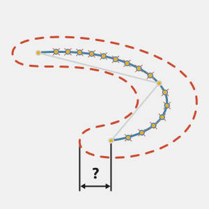
- Overlap distance - defines an amount of overlap between the points and which the toolpath disengages, and then reengages to maintain the up, or down, cutting.
- Minimum height change - defines the height difference defining the up/down range.
- Start corner - determines in which of the four corners the operation should begin. This option is available when the High speed option in the Pattern group is not selected.
- • Lower Left - defined as the corner with the smallest value position in the X,Y axes.
- • Lower Right - defined as the corner with the smallest Y value, and largest X value along the axes.
- • Upper Left - defined as the corner with the largest Y value, and smallest X value along the axes.
- • Upper Right - defined as the corner with the largest value position in the X,Y axes.
- Direction for one way machining - controls how the tool cuts into the material.
- Climb - tool movement and the spindle rotation have the same direction.
- Conventional - tool movement is opposite to the spindle rotation.
- Start
Point - allows you to define desired start position for roughing toolpath. Actual start position will be located on the closest cut to user defined point. Available for 'Offset' and 'Adaptive' roughing types.
Select the check box when
specifying a toolpath starting point. Click Start Point to open the Start Point Parameters
dialog box, and enter the coordinates or select a point to act as the start point.
Clear the check box when not specifying a toolpath
starting point.
Surface Quality
- Cut tolerance
- determines how accurate the toolpath must be in relation to the
selected geometry.
Tip: You can
reduce the cut tolerance value, for example from 0.0005 to 0.005, to speed
up the toolpath calculation while creating and modifying your toolpath.
Once your are happy with the result, you can then set it back to the original
tolerance to calculate the toolpath before posting the output.
- Advanced
- opens the Advanced options for Surface Quality dialog allowing control over the output type, arc fits, and point distribution.
Advanced options for Surface Quality
- Output type - determines how the surface quality is controlled.
Fit arcs and point distribution - allows for control over the arc output and point distribution.
Polygonize and point distribution - allows for control over point distribution.
High surface quality - handles control of the surface quality without user input.
- Planes - determines the planes in which toolpaths arcs will be fitted.
-
Arc fit - select to output arcs in the toolpath.
-
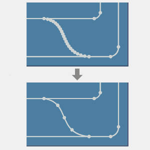
Arc fit links - allows for the reduction in the number of points on blend splines by arc-fitting the blend spline links.
-
Arc fit factor - determines the tolerance of the arc fit.
Point distribution
-
Maximum distance - Selecting this check box allows you to set a maximum distance between toolpath points, as well as control over the maximum angle deviation between points.
-
Minimum distance - Selecting this check box allows you to set a minimum distance between toolpath points, as well as control over the allowable deviation, or tolerance, between points.
Related Topics
The Multiaxis Wizard


 - Clicking the ellipses button opens the Machining direction dialog, allowing you to adjust the orientation of the toolpath plane.