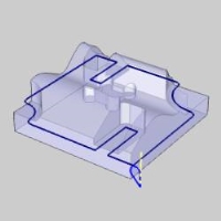
How to Use Loop Selection
Introduction
This topic explains how to use the loop selection options when selecting the edges of solid or surface geometry to use as wireframe selections for machining features. There are two loop selection options: Constant Z and Loop Selection.
Selection
Constant Z
The Constant Z option is used to select one or more loops from the model that contain a constant Z-axis value along the entire loop.
Note: The Constant Z loop selection option uses the Z-axis of the machining origin(which is defined in the Machine Setup) and not the Z-axis of the WCS (world coordinate system).
Loop Selection
The Loop Selection option is used to select one or more continuous loops from the model. These loops may or may not have a constant Z-axis value along the entire loop. When using the Loop Selection option, the software highlights two loops. After the two loops are highlighted, you click the loop that you want to keep at any location that is not shared between the two possible loops. The other loop is removed and the desired loop is selected. The following sections explain how to use Loop Selection.
When to Use Loop Selection
The following list gives a few examples of when you can use loop selection. The Constant Z option is useful for selecting 2D chains with a constant Z-axis value. The Loop Selection option is useful for selecting 3D chains or any loop that does not have a constant Z-axis value.
Loop selection is used:
- When selecting feature geometry for 2-axis machining features
- When selecting a boundary for 3-axis features or operations
- When selecting geometry or boundaries for Multiaxis features
Using Constant Z
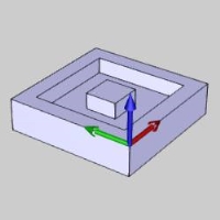
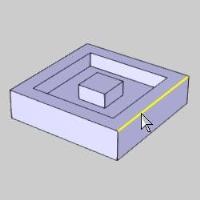
The following image shows an example part model and the machining origin(work offset) on the part.
-
During selection mode, point to the surface edge of the loop that you want to select.
-
While the surface edge displays in the current Highlight color, right-click (click with the right mouse button) to display a shortcut menu.
-
In the shortcut menu, click Constant Z.
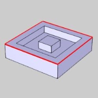
The outer loop of the model is selected.
To confirm the selection, click ![]() OK.
OK.
The selection shown can be used to face the top of the part, profile the outside of the part, or even apply a chamfer or corner rounding operation to the top edge.
About the Z Axis Direction
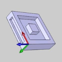
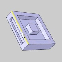
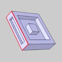
The following image shows the same part model with a second work offset defined to face and pocket the side of the part. The new machining origin Z-axis is not the same orientation as the first.
-
During the geometry selection, point to a surface edge, right-click, and click Constant Z.
-
To confirm the selection, click
 .
.
Again, the selection shown can be used to apply a face, profile, chamfer, or corner round operation to the feature.
Multiple Loop Selection
The loop selection options are designed to assist you when selecting solid and/or surface edges and you can continue to add or remove selections for features in which more than one contour or profile is needed.
-
For the next example, we have a part with multiple pockets to select for a 2-axis feature.
During geometry selection, point to the surface edge and right-click.
In the shortcut menu, click Constant Z.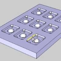
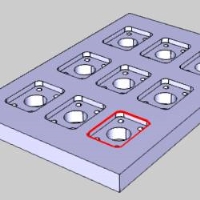
-
Repeat this process as many times as needed to select all of the feature geometry.
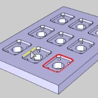
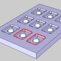
-
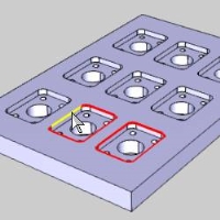
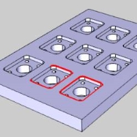
During the selection, we realize that we want to select just one pocket and then use a Toolpath Pattern to handle the remaining pockets.
You can click to remove selections from the automatically selected loops.
Removing Loop Selections
In addition to the ability to make multiple selections, you can also add or remove selections when using the loop selection options.
-
Point to the unwanted entity, and click to remove it from the current selection.
-
You can repeat this process to remove all unwanted entities.
-
After removing the unwanted selections, click
 to confirm the selection.
Note: To remove an entire loop from selection, simply repeat the process. If a loop is selected, right-clicking an edge of the selection and selecting Constant Z will deselect that loop.
The Constant Z option is extremely useful when selecting 2D loops. When you need to select 3D loops from a model, you can use the Loop Selection option.
Using Loop Selection
The Loop Selection option is used to select a continuous loop from the geometry that may or may not have a constant Z-axis value. What is important to understand about using Loop Selection is that there are often two loops to choose from when selecting a surface edge. In this scenario, when you click Loop Selection, the software highlights both of the loops. It is then up to you to select the loop that you want to keep. The proper way to do this is explained next.
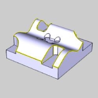
For the part in this example, we want to select the outer profile of the part to create a profile finish operation. The part geometry contains wavy surfaces which can't be selected using Constant Z. Furthermore, there is another pocket in the center of the top surface. If we selected the top surface for the feature and let the software extract the edges, then the pocket in the center would be included in the selection. Loop Selection makes it much easier to select only the desired outer boundary as explained next.
-
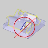
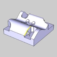
During selection mode, point to the surface edge of the loop that you want to select, and right-click.
-
In the shortcut menu, click Loop Selection.
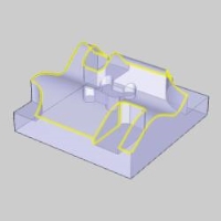
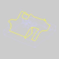
Two potential loops are highlighted on the model.
One loop is the outside edge of the top surface, and the other loop is the edge of the vertical face on the side of the open pocket. The next step is to select the loop that you want to keep.
The Importance of Transparency and Shading
Before moving on with the example, there are a few helpful tips to assist you in proper loop selection. When we clicked Loop Selection, the software automatically highlighted two potential loops based on the surface edge that we selected. The first tip is to use Transparency to better show the two potential loops.
To better view the loops by making the part model transparent:
- In the document toolbar, click Transparent. (You can also press T, to toggle the transparency status of the part.)
By making the part transparent, it is much easier to view the two loops. This makes selecting the loop that you want to keep much easier, as explained in the next section of this example.
In addition to the model transparency, you may also want turn on and off the Shading of the part model. This is another way to make the two potential loops easier to view. (Turning off shading can also make it easier to select edges from complex solid/surface geometry.)
To better view the loops and aid in surface edge selection:
-
In the document toolbar, click
 Shaded. (You can also press S to toggle the shaded status of the model.)
The tips provided about using the Transparent and Shaded View options can be useful in many situations when selecting geometry for machining features, not just loop selection.
Select the Loop to Keep
In order to select the loop that you want to keep, click any entity along the desired loop that is not shared between the two loops. When you click the loop to keep, the other loop is removed from the selection and you can then confirm the selection (you can also continue to make selections or remove selections if needed).
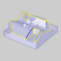
For our current example, there is only one shared entity along the two currently selected loops.
The following image shows the entity that is shared between the two loops (shown in blue).
Clicking this shared entity does not change the selection.
You can click anywhere else to select the loop that you want to keep.
-
Click the loop that you want to keep anywhere along the chain that isn't shared with the other loop.
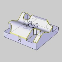
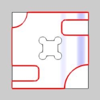
The unwanted loop is removed and the desired loop is now selected.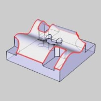
-
To confirm the selection, click
 .
.
With the selection made in this example, a profile (rough or finish) pass can now be applied to the selected loop.
Notice that we have selected geometry from a 3D model that is being used in the 2 Axis Wizard. To learn more, view the Related Topics links.
The loop selection tools are very helpful when you need to select surface edges for machining features.
This concludes the example.


