 Copy Face
Introduction
This topic will explain the Copy Face function, will explain where to find the function, and explain the options found in it. This topic will also explain creation with quick steps and examples, and provide links to related topics.
The Copy Face Function
The Copy Face function is used to duplicate face from existing surfaces or solids without the need to unstitch those surfaces the faces are being replicated from. To perform the function, you add the faces being replicated to the Selected Geometry list, select whether or not the duplicates should be stitched together, and confirm to create the duplicates.
Navigation
To open Copy Face:
- In the Surfaces group, of the Create 3D tab, click
 Copy Face.
The parameters display in the Data Entry Manager.
The Data Entry Parameters
Selected Geometry
|
|
|
| The list will display all entities currently selected for the function. | |
Option
-
Stitch Faces - determines whether resulting faces sharing a common edge from a surface body are stitched together.
 - With this option cleared, none of the resulting faces will be stitched together by the function.
 - With this option selected, faces sharing a common edge from the same surface body will be stitched together.
- OK - finalizes the function.
- Cancel - exits the function.
Quick Steps - Copy Face
When creating duplicate faces using the Copy Face function, you select the faces to be copied to add them to the Selected Geometry list, select the Stitch Faces option as needed, and click OK.
- Open the function.
The Selected Geometry list automatically has focus. - Select the faces to be duplicated.
- Select, or clear, the Stitch Faces option.
- Click OK to create the faces.
The feature is added to the CAD Tree. - Repeat as necessary.
- Click Cancel to exit the function.
Example
This example will demonstrate how to use the Copy Face function on a primitive solid with added chamfers.
Note: In the images below, both the Show Axis X-Yand Show Gnomon toggles have been disabled in the Axis X-Y group of the Settings Part > Display dialog.
Part 1) Create the cube
-
Open a new file.
-
Press Ctrl+7 to enter an ISO2 view.
-
In the Primitives group, of the Create 3D tab, click
 Cube.
Cube.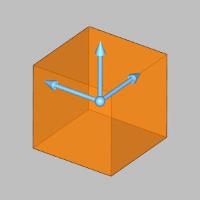
The preview appears. -
Click OK to create a cube with the default values.
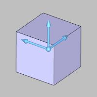
The cube is created. -
Click Cancel to exit the dialog.
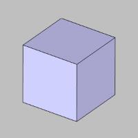
The dialog closes.
Part 2) Add the chamfers
-
In the Corners group, of the Create 3D tab, click
 Solid Chamfer.
The Solid Chamfer dialog opens in the Data Entry Manager. -
In the Parameters section, select the check box for Whole Solid.
-
Select the cube.
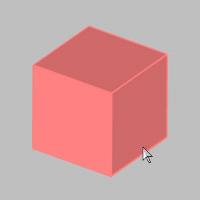
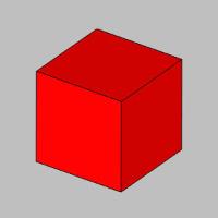
The cube is added to the Selected Geometry list. -
Click the Show Preview button.
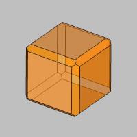
The preview shows the result using the default Chamfer Width value. -
Click OK to create the chamfers.
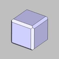
Part 3) Copy faces without Stitch Faces
Copying the faces
- In the Layers Manager, click
 Add NewLayer.
A new layer is created.This new layer becomes the active layer automatically. - In the Surfaces group, of the Create 3D tab, click
 Copy Face.
 - With the Stitch Faces option cleared, select the three closest chamfers.
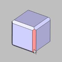
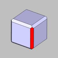
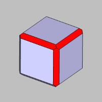
- Click OK to create the copies.
- Click Cancel to exit the function.
Viewing the results
-
Hide the original CAD layer.
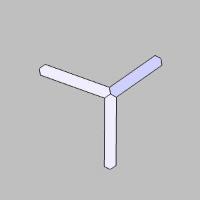
The original model is hidden, leaving only the new copies visible. -
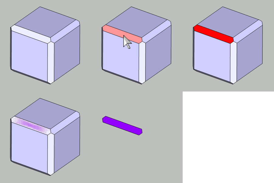
Enter Selection Mode, and highlight one of the chamfers.
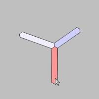
Notice each of these three faces are independent bodies. While these faces share common edges from the same body, clearing the Stitch Faces option causes them to be created as separate bodies. -
Set the CAD layer to visible, and hide Layer-1.

Part 4) Copy faces using Stitch Faces
Copying the faces
For this portion of the example, we copy faces which do not share a common edge using the Stitch Faces option.
- In the Layers Manager, click
 Add NewLayer.
A new layer is created. This new layer becomes the active layer automatically. - In the Surfaces group, of the Create 3D tab, click
 Copy Face.
 - Select the check box for the Stitch Faces option.
- Select the three closest main faces of the cube.
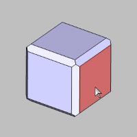
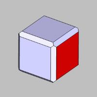
- Click OK to create copies.
- Click Cancel to exit the function.
Viewing the results
-
Hide the original CAD layer.
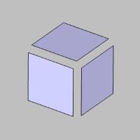
The original model is hidden, leaving only the new copies visible. -
Enter Selection Mode, and highlight one of the faces.
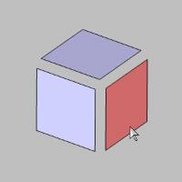
Notice each of these three faces are independent bodies. While we used the Stitch Faces option, these faces do not share common edges, which causes them to be created as separate bodies. -
Set the CAD layer to visible, and hide Layer-2.

Copying the faces
In this portion of the example, we use the Stitch Faces option while copying several faces which share a common edge, and one that does not.
- In the Layers Manager, click
 Add NewLayer.
A new layer is created. This new layer becomes the active layer automatically. - In the Surfaces group, of the Create 3D tab, click
 Copy Face.
 - Leave the Stitch Faces option selected.
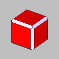
- Select the faces seen in the images below.
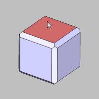
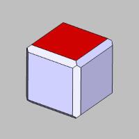
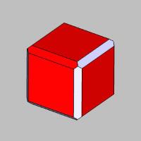
- Click OK to create copies.
- Click Cancel to exit the function.
Viewing the results
-
Hide the original CAD layer.
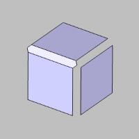
The original model is hidden, leaving only the new copies visible. -
Enter Selection Mode, and highlight the face on the right.
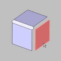
Notice this face is a separate body. While we used the Stitch Faces option, this face does not share a common edge with any of the others, which causes it to be created as separate body. -
Highlight one of the other faces.
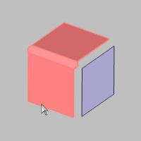
Notice with the Stitch Faces option, each surface with a shared edge from a single body is created already stitched together as a single body.
This concludes the example.


 (Delete All)
- removes all entities from the Selected Geometry list.