


 Rectangle 2 Points- Center
Introduction
This topic will explain the Rectangle 2 Points - Center function, will explain where to find the function, and explain the options found in it. This topic will also give a brief description of Dynamic Drawing, the Snap Increment function, explain creation with quick steps, and provide links to related topics.
The Rectangle 2 Points - Center Function
The Rectangle 2 Points - Center function is used to create rectangles using sketching, or a combination of both.
Dynamic Drawing
This function supports Dynamic Drawing which allows you to use a combination of sketching and data entry to create the entities. Prior to confirming the desired result in the function, an adjustable preview is visible. These previews can be modified using data entry. The benefit of Dynamic Drawing is that you can quickly place and adjust the size to get the approximate result, and then use data entry to update to the exact dimensions, and coordinate values as needed.
|
Planes in Modify Mode |
Final Entities |

|
|
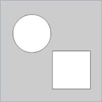
In the images above, we see the preview of surfaces which can still be adjusted, followed by those same surfaces after they are finalized.
Snap Increment
This function support the use of the snap increment when selecting the location of the entities. The snap increment allows you to get precise results when using mouse selection and helps to reduce data entry modifications.
To learn more, view Snap Increment.
Navigation
To use the Rectangle 2 Points - Center creation option, for the Rectangular Plane:
-
In the Surfaces group, of the Create 3D ribbon, click the down arrow under
 Planar, and select
  Rectangular Plane.
Once in the feature, select the Rectangle 2 Points - Center Creation Option.
The parameters display in the Data Entry Manager.
The Data Entry Parameters
 Creation Options
![]()
![]()
![]()
![]()
![]()
Parameters
Dimensions
- Length (X) - sets the length of the rectangle along the X-axis of the Active UCS.
- Width (Y) - sets the width of the rectangle along the Y-axis of the Active UCS.
- Angle - allows the rectangle to be rotated around the origin.
Base Point
The Base Point determines the coordinate location of the rectangle using the XYZ coordinates of the active UCS. The selected origin location determines where the origin is on the entity.
Tip: The XYZ coordinates are in reference to the active UCS, or user coordinate system.
Corner Type
-
 Radius - creates the rectangle
with round corners using the Radius value.
Radius - creates the rectangle
with round corners using the Radius value. -
 Chamfer Length - creates the rectangle
with chamfered corners using the Chamfer value.
Chamfer Length - creates the rectangle
with chamfered corners using the Chamfer value.

- OK - finalizes the function.
- Cancel - exits the function.
Quick Steps - Rectangle 2 Points - Center
-
Open the function and choose the
Rectangle 2 Points - Center Creation Option. -
Click a snap point or anywhere in the graphics area to set the center point of the rectangle.
You can modify the snap increment value or turn it off while selecting locations with the mouse. -
Movethe mouse pointer and click a snap point or anywhere to set the width and length or the rectangle.
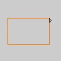

Therectangle changes from the Preview color to the Entity color and displays with a greater line thickness to show it is the active entity. -
This is now the active entity, which means that it is not fully defined.
You can then modify the Data Entry parameters to update the active entity. -
Dynamic Drawing allows you to update the Data Entry parameters to modify the active rectangle.
After updating the Data Entry parameters, to finish the active entity, you can click OK or start sketching the next rectangle.
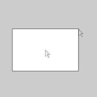
In the images above we see the finished surface and the finished surface with the points used to create it.
When you don't need to update the Data Entry parameters, you can just click to start the next rectangle.
Note: There are many ways to finish the active entity: click OK, press Spacebar, or click in the graphics area to start the next rectangle.
-
Repeat this process for all rectangles to be created.
-
To close the function, click Cancel.