


The Broken Tool Cycle
Introduction
This topic will explain the Broken Tool cycle, will describe how to access it, will explain the options found in it, and will explain how to use it with quick steps.
The Broken Tool Cycle
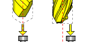
This cycle is used to check the length of a rotating tool for a broken tool condition.
The cycle also checks for a ‘long tool’ condition, where the tool has possibly pulled out during machining. The spindle returns to a safe position and then automatically moves the tool to a position above the stylus prior to checking its length.
Navigation
To access the Broken Tool cycle:
- In the CAM Tree, right-click Milling Tools, and select Tool Crib.
The Tool Crib dialog launches in the Data Entry Manager. - Add all tools needed for the job.
- Click OK.
The Tool Crib dialog closes. - In the CAM Tree, locate the desired Machine Setup for the Probing cycle, right-click the Machine Setup, and select Probing.
The Probing dialog launches in the Data Entry Manager. - In the Machining Strategy list of the Feature page, click the Contact Tool Setter operation.
The Contact Tool Setter operation replaces the Measure operation in Current Operations list. - Click the Operations(s) tab.
- Select the appropriate cycle from the drop down list in the Cycle section of the Parameters tab.
The Data Entry Parameters
 Parameters
Tool
- Tool Name -This drop down will list all the tools currently in the tool crib.
- Override Tool Data
 - With this check box selected, you will be able to update the Tool Number and Tool Diameter.
 - With this check box cleared, editing of the Tool Number and Tool Diameter is unavailable.
 - Tool Number - Lists the Tool Number of the currently selected tool.
- Tool Diameter - Lists the diameter of the currently selected tool. - With this check box selected, the tool diameter will be output to offset the tool before contacting the stylus. - With this check box cleared, the tool will be centered over the stylus.
- Broken Tool Flag - Tool out of tolerance flag. Use this flag to prevent a tool OUT OF TOLERANCE alarm from being raised. Enter the value to be called out with the flag.
Options
- Tool Offset - Tool length offset number. This is the offset location in which the measured tool length is stored when it needs to be different from the active tool number.
- Tolerance - When this input is used, the tool offset is not updated if the tool length is found to be out of tolerance.
- Overtravel Distance - The default overtravel distance and radial clearance. Overtravel is the distance beyond the point at which contact should have been made with the stylus the tool is permitted to move before an out of tolerance alarm is initiated.
- Experience Value (Diameter) - This value is the difference between the measured radius/diameter of the tool and the actual radius/diameter when the tool is under load during the cutting process. It is used to refine the measured radius/diameter, based on previous experience of how the effective radius/diameter differs from the measured radius/diameter when the tool is under load.
- Diameter Offset - determines the diameter offset to update in the cycle. By default this value matches the current tool number.
- Rapid Position - is the height above the stylus to rapid to.
- Clearance Position - The tool moves to this clearance position above the stylus before and after the cycle is run.
Quick Steps - Broken Tool
- In the CAM Tree, right-click Milling Tools, and select Tool Crib.
The Tool Crib dialog launches in the Data Entry Manager. - Add all tools needed for the job.
- Click OK.
The Tool Crib dialog closes. - In the CAM Tree, locate the desired Machine Setup for the Probing cycle, right-click the Machine Setup, and select Probing.
The Probing dialog launches in the Data Entry Manager. - In the Machining Strategy list of the Feature page, click the Contact Tool Setter operation.
The Contact Tool Setter operation replaces the Measure operation in Current Operations list. - Click the Operations(s) tab.
- Select the appropriate cycle from the drop down list in the Cycle section of the Parameters tab.
- In the Parameter section, select the tool and adjust the select the Override Tool Data check box is necessary.
If you select the Override Tool Data check box, adjust the Tool Number and Tool Diameter values as needed. - In the Options section, select the check boxes for any and all calls required in the output and set their values as needed.
- Select the Raw Text tab in order to output any macros or code manually.
- In the Raw Text tab, select the Output in NC Program check box.
- Enter the data to be output in the text field.
- Click OK.
The operation is added to the CAM Tree.
Example 1 - Broken Tool - On Center (Alarm)
By default, If a broken tool, or a long tool is detected, the controller will alarm out and the operator will need to step in to decide how to handle.
In this example we:
- Setup the Tool Crib.
- Select the Broken Tool - Plunge cycle.
- Select the tool.
Part 1) Setting up the Tool Crib
- In the CAM Tree, right-click Milling Tools, and select Tool Crib.
The Tool Crib dialog launches in the Data Entry Manager. - Add all tools needed for the job.
- Click OK.
The Tool Crib dialog closes.
Part 2) Selecting the Diameter cycle
- In the CAM Tree, locate the desired Machine Setup for the Probing cycle, right-click the Machine Setup, and select Probing.
The Probing dialog launches in the Data Entry Manager. - In the Machining Strategy list of the Feature page, click the Non-Contact Tool Setter operation.
The Non-Contact Tool Setter operation replaces the Measure operation in Current Operations list. - Click the Operations(s) tab.
By default the Tool Length is the selected cycle.
- Click the drop down and select Broken Tool from the list.
Part 3) Selecting the Tool to be set
- In the Parameters section, select the tool to be set from the drop down list.
By default the Tool Offset is set to the tool number of the selected tool. - Click OK to create the Tool Diameter cycle and exit the dialog.
Example 2 - Broken Tool - On Center (No Alarm)
When preventing the alarm from being raised, creating if/then statements in the Raw Text tab of the Operation(s) page is necessary. This will allow you to program a set of steps for each possible outcome of the cycle.
In this example we:
- Setup the Tool Crib.
- Select the Tool Diameter cycle.
- Select the tool.
- Prevent the alarm from being called.
- Create the raw text needed for the results of the cycle.
Part 1) Setting up the Tool Crib
- In the CAM Tree, right-click Milling Tools, and select Tool Crib.
The Tool Crib dialog launches in the Data Entry Manager. - Add all tools needed for the job.
- Click OK.
The Tool Crib dialog closes.
Part 2) Selecting the Tool Diameter cycle
- In the CAM Tree, locate the desired Machine Setup for the Probing cycle, right-click the Machine Setup, and select Probing.
The Probing dialog launches in the Data Entry Manager. - In the Machining Strategy list of the Feature page, click the Non-Contact Tool Setter operation.
The Non-Contact Tool Setter operation replaces the Measure operation in Current Operations list. - Click the Operations(s) tab.
By default the Tool Length is the selected cycle.
- Click the drop down and select Broken Tool from the list.
Part 3) Selecting the Tool to be checked
- In the Parameters section, select the tool to be set from the drop down list.
Part 4) Preventing the Alarm
- In the Options section, select the check box for Broken Tool Flag.
This prevents the alarm from being called.
Part 5) Entering the Raw Text
- Select the Raw Text tab.
- Select the check box for Output in NC Program.
By default the Add Line Numbers check box is already selected. - In the text field, enter all if/then statements, macros, and/or code to handle the following possibilities:
Good Tool
Broken Tool
Long Tool - Click OK to create the Tool Diameter cycle and exit the dialog.