


The Cutting Edge Check Cycle
Introduction
This topic will explain the Cutting Edge Check cycle, will describe how to access it, will explain the options found in it, and will explain how to use it with quick steps.
The Cutting Edge Check Cycle
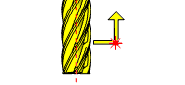
This cycle is used for checking the cutting edges of a tool. It checks for either missing or damaged teeth or for excessive run-out of the cutter.
Before a tool is checked for missing teeth or excessive run-out, it is first set for radius/diameter. The diameter cutting edge check cycle then moves the rotating tool into the beam until the teeth interfere with the beam by the cutting edge run-out tolerance value. This value is defined by the K input.
The spindle speed is calculated from the minimum pulse signal delay (#115) of the NCTS system and the number of teeth on the cutting tool. This ensures that when each tooth enters the beam, a permanent beam cut signal is held unless a tooth is either missing or is out of tolerance. The beam cut signal is monitored for a minimum of two revolutions.
Navigation
To access the Cutting Edge Check cycle:
- In the CAM Tree, right-click Milling Tools, and select Tool Crib.
The Tool Crib dialog launches in the Data Entry Manager. - Add all tools needed for the job.
- Click OK.
The Tool Crib dialog closes. - In the CAM Tree, locate the desired Machine Setup for the Probing cycle, right-click the Machine Setup, and select Probing.
The Probing dialog launches in the Data Entry Manager. - In the Machining Strategy list of the Feature page, click the Non-Contact Tool Setter operation.
The Non-Contact Tool Setter operation replaces the Measure operation in Current Operations list. - Click the Operations(s) tab.
- Select the appropriate cycle from the drop down list in the Cycle section of the Parameters tab.
The Data Entry Parameters
 Parameters
Tool
- Tool Name -
This drop down will list all the tools currently in the tool crib.
- Override Tool Data
 - With this check box selected, you will be able to update the Tool Number and Tool Diameter.
 - With this check box cleared, editing of the Tool Number and Tool Diameter is unavailable.
 - Tool Number - Lists the Tool Number of the currently selected tool.
- Tool Diameter - Lists the diameter of the currently selected tool. - With this check box selected, the tool radius will be output for the cycle. - With this check box cleared, default maximum tool radius will be used for the cycle.
Tip: Select the Tool Diameter check box to output the proper radius for the tool.
- Tool Setting - Determines whether the cycle updates offsets, and if so which.Choose between:
- Tool Radius/Diameter - updates the Radius/Diameter offset.
- Tool Length and Diameter - updates the Length and the Radius/Diameter offsets.
- No Offset Update - does not update any offsets.
- Tool Radius/Diameter - updates the Radius/Diameter offset.
- Number of Flutes - sets the number of flutes to determine at which spindle speed the cycle should be run.
Options
- Tool Offset - Tool length offset number. This is the offset location in which the measured tool length is stored when it needs to be different from the active tool number.
- Broken Tool Flag - Tool out of tolerance flag. Use this flag to prevent a tool OUT OF TOLERANCE alarm from being raised. Enter the value to be called out with the flag.
- Overtravel Distance - The default overtravel distance and radial clearance. Overtravel is the distance through the beam that the tool is permitted to move before a BEAM NOT CUT alarm is initiated. Radial clearance is the distance between the tool and the beam when moving down the side of the beam.
- Spindle Speed - The default spindle speed. Measurement cycles are optimized for a spindle speed of 3000 r/min. Some tools – for example, those that are unbalanced or large – must be run at speeds less than 3000 r/min. This is the responsibility of the user. Use the ‘S’ input to set the speed. Measurement cycle times increase with slower speeds. The minimum speed is 800 r/min.
- Search Distance - Search distance for a high spot in the spindle axis. This defines a search distance above the Z input measuring height that is used to find a radial high spot on the cutter. It is suitable for single-point boring bars and cutters with irregular radial profiles. Entering a position number will search for the highest point in a convex diameter, while using a negative value will search for the lowest point in concave diameter.
- Measuring Height - Measuring height of the tool. This is the Sp-axis position from the end face of the tool at which measurement of the radius/diameter takes place.
- Feedrate per Rev. - Feedrate-per-rev. for cylinder profile checking when using the X input.
- Run-out Tolerance - Tolerance value that defines when the tool cutting edge run-out is excessive.
Quick Steps - Cutting Edge Check
- In the CAM Tree, right-click Milling Tools, and select Tool Crib.
The Tool Crib dialog launches in the Data Entry Manager. - Add all tools needed for the job.
- Click OK.
The Tool Crib dialog closes. - In the CAM Tree, locate the desired Machine Setup for the Probing cycle, right-click the Machine Setup, and select Probing.
The Probing dialog launches in the Data Entry Manager. - In the Machining Strategy list of the Feature page, click the Non-Contact Tool Setter operation.
The Non-Contact Tool Setter operation replaces the Measure operation in Current Operations list. - Click the Operations(s) tab.
- Select the appropriate cycle from the drop down list in the Cycle section of the Parameters tab.
- In the Parameter section, select the tool and adjust the select the Override Tool Data check box is necessary.
If you select the Override Tool Data check box, adjust the Tool Number and Tool Diameter values as needed. - In the Options section, select the check boxes for any and all calls required in the output and set their values as needed.
- Select the Raw Text tab in order to output any macros or code manually.
- In the Raw Text tab, select the Output in NC Program check box.
- Enter the data to be output in the text field.
- Click OK.
The operation is added to the CAM Tree.
Example 1 - Cutting Edge Check (Alarm)
By default, If a tool is found to be out of tolerance, the controller will alarm out and the operator will need to step in to decide how to handle.
In this example we:
- Setup the Tool Crib.
- Select the Cutting Edge Check cycle.
- Select the tool.
- Set the Search Distance and Measuring Height.
Part 1) Setting up the Tool Crib
- In the CAM Tree, right-click Milling Tools, and select Tool Crib.
The Tool Crib dialog launches in the Data Entry Manager. - Add all tools needed for the job.
- Click OK.
The Tool Crib dialog closes.
Part 2) Selecting the Cutting Edge Check cycle
- In the CAM Tree, locate the desired Machine Setup for the Probing cycle, right-click the Machine Setup, and select Probing.
The Probing dialog launches in the Data Entry Manager. - In the Machining Strategy list of the Feature page, click the Non-Contact Tool Setter operation.
The Non-Contact Tool Setter operation replaces the Measure operation in Current Operations list. - Click the Operations(s) tab.
By default the Tool Length is the selected cycle.
- Click the drop down and select Cutting Edge Check from the list.
Part 3) Selecting the Tool to be set
- In the Parameters section, select the tool to be set from the drop down list.
By default the Tool Offset is set to the tool number of the selected tool.
Part 4) Setting the Search Distance and Measuring Height
- In the Options section, select the check box for Search Distance.
- In the Search Distance text box, enter the total length to be checked along the cutting edge of the tool.
- In the Options section, select the check box for Measuring Height.
- In the Measuring Height text box, enter the height from the tip of the tool at which point the cutting edge check should begin.
- Click OK to create the Cutting Edge Check cycle and exit the dialog.
Example 2 - Cutting Edge Check (No Alarm)
When preventing the alarm from being raised, creating if/then statements in the Raw Text tab of the Operation(s) page is necessary. This will allow you to program a set of steps for each possible outcome of the cycle.
In this example we:
- Setup the Tool Crib.
- Select the Cutting Edge Check cycle.
- Select the tool.
- Set the Search Distance and Measuring Height.
- Prevent the alarm from being called.
- Create the raw text needed for the results of the cycle.
Part 1) Setting up the Tool Crib
- In the CAM Tree, right-click Milling Tools, and select Tool Crib.
The Tool Crib dialog launches in the Data Entry Manager. - Add all tools needed for the job.
- Click OK.
The Tool Crib dialog closes.
Part 2) Selecting the Cutting Edge Check cycle
- In the CAM Tree, locate the desired Machine Setup for the Probing cycle, right-click the Machine Setup, and select Probing.
The Probing dialog launches in the Data Entry Manager. - In the Machining Strategy list of the Feature page, click the Non-Contact Tool Setter operation.
The Non-Contact Tool Setter operation replaces the Measure operation in Current Operations list. - Click the Operations(s) tab.
By default the Tool Length is the selected cycle.
- Click the drop down and select Cutting Edge Check from the list.
Part 3) Selecting the Tool to be set
- In the Parameters section, select the tool to be set from the drop down list.
By default the Tool Offset is set to the tool number of the selected tool.
Part 4) Setting the Search Distance and Measuring Height
- In the Options section, select the check box for Broken Tool Flag.
This prevents the alarm from being called. - In the Options section, select the check box for Search Distance.
- In the Search Distance text box, enter the total length to be checked along the cutting edge of the tool.
- In the Options section, select the check box for Measuring Height.
- In the Measuring Height text box, enter the height from the tip of the tool at which point the cutting edge check should begin.
Part 5) Entering the Raw Text
- Select the Raw Text tab.
- Select the check box for Output in NC Program.
By default the Add Line Numbers check box is already selected. - In the text field, enter all if/then statements, macros, and/or code to handle the following possibilities:
Good Tool
Broken Tool
Long Tool - Click OK to create the Tool Diameter cycle and exit the dialog.
Tip: To learn about how to use the Broken Tool Flag option, see the examples in the Broken Tool - Plunge and/or Broken Tool - Solid topics.