


The Radius Profile Checking Cycle
Introduction
This topic will explain the Radius Profile Checking cycle, will describe how to access it, will explain the options found in it, and will explain how to use it with quick steps.
The Radius Profile Checking
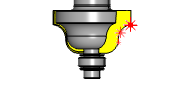
This cycle is used to verify the specified form of a profiled cutting tool. It is particularly suitable for ball nose cutters, and cutters with a corner radius.
The specified form of the profile can be checked either internally, for the detection of missing or broken teeth and inserts; or externally, for detection of misaligned inserts and incorrect forms.
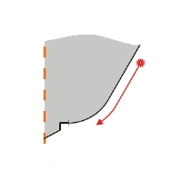
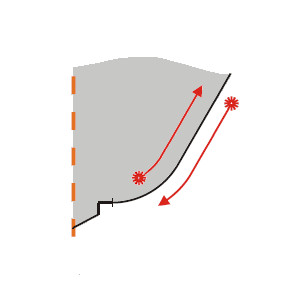
The tool is retracted to the home position for safety before each profile check unless a secondary profile check is to be performed on the same tool. The tool is positioned over the laser beam and is moved first to the longest tool position, then to the profile start position with the spindle rotating. The defined cutter profile is traced at the checking feedrate.Finally, the tool is retracted out of the beam.
An error flag is always set and an alarm is optionally generated if the cutter is out of tolerance.
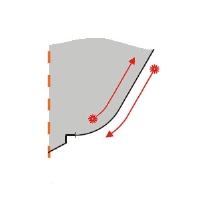
If both + and – tolerance checking is specified, the cutter is repositioned after the negative (–) tolerance check and a reverse profile check is made along the profile.Finally, the tool is retracted.
Navigation
To access the Broken Tool - Solid Tool cycle:
- In the CAM Tree, right-click Milling Tools, and select Tool Crib.
The Tool Crib dialog launches in the Data Entry Manager. - Add all tools needed for the job.
- Click OK.
The Tool Crib dialog closes. - In the CAM Tree, locate the desired Machine Setup for the Probing cycle, right-click the Machine Setup, and select Probing.
The Probing dialog launches in the Data Entry Manager. - In the Machining Strategy list of the Feature page, click the Non-Contact Tool Setter operation.
The Non-Contact Tool Setter operation replaces the Measure operation in Current Operations list. - Click the Operations(s) tab.
- Select the appropriate cycle from the drop down list in the Cycle section of the Parameters tab.
The Data Entry Parameters
 Parameters
Tool
- Tool Name -
This drop down will list all the tools currently in the tool crib.
- Override Tool Data
 - With this check box selected, you will be able to update the Tool Number and Tool Diameter.
 - With this check box cleared, editing of the Tool Number and Tool Diameter is unavailable.
 - Tool Number - Lists the Tool Number of the currently selected tool.
- Tool Diameter - Lists the diameter of the currently selected tool.
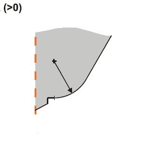
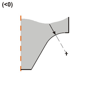
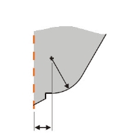
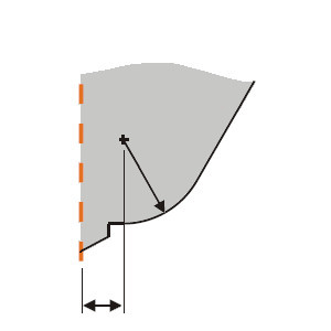
- Profile Radius - determines the radius to measure.Use a positive value for a convex radius and a negative value for a concave radius.
| Positive Radius | Negative Radius |
|
|
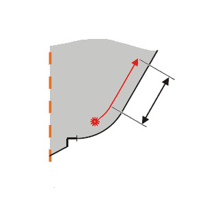
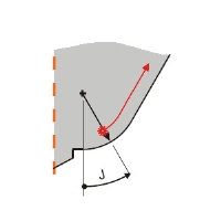
- Linear Distance - determines the tangential distance beyond the cutter profile to measure.

Options
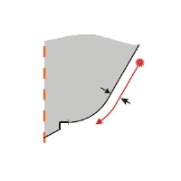
- Check Cutter Profile Option - determines which side the tool is measured on and whether a retract is used.Choose between:
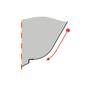
- Along the Negative - measures the tool along a negative offset of the tool profile based on the specified tolerance.

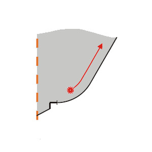
- Along the Positive - measures the tool along a positive offset of the tool profile based on the specified tolerance.
- Both - measures the tool along offsets of the tool profile based on the specified tolerance.
- Along the Negative (No Retract) - measures the tool along a negative offset of the tool profile based on the specified tolerance. The tool does not retract after the profile check.
- Along the Positive (No Retract) - measures the tool along a positive offset of the tool profile based on the specified tolerance. The tool does not retract after the profile check.
- Both (No Retract) - measures the tool along offsets of the tool profile based on the specified tolerance. The tool does not retract after the profile check.
- Along the Negative - measures the tool along a negative offset of the tool profile based on the specified tolerance.
- Tool Offset - Tool length offset number. This is the offset location in which the measured tool length is stored when it needs to be different from the active tool number.
- Broken Tool Flag - Tool out of tolerance flag. Use this flag to prevent a tool OUT OF TOLERANCE alarm from being raised. Enter the value to be called out with the flag.
- Spindle Speed - The default spindle speed. Measurement cycles are optimized for a spindle speed of 3000 r/min. Some tools – for example, those that are unbalanced or large – must be run at speeds less than 3000 r/min. This is the responsibility of the user. Use the ‘S’ input to set the speed. Measurement cycle times increase with slower speeds. The minimum speed is 800 r/min.
- Feedrate per Rev.- Feedrate specified as feed/rev for profile checking.
- Run-out Tolerance - Tolerance value that defines when the cutter profile is out of limits.
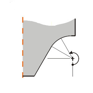
- Radial Distance - Radial distance to the cutter radius center.
- Safety Plane - The distance along the spindle-axis by which the tool is retracted from the beam.

- Number of Flutes - sets the number of flutes to determine at which spindle speed the cycle should be run.
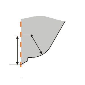
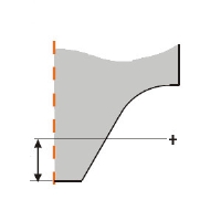
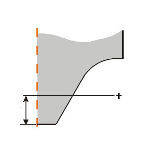
- Check Height - The height to the first profile checking position.
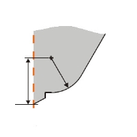
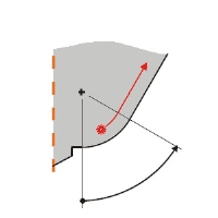
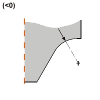
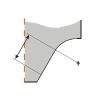
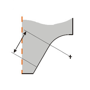
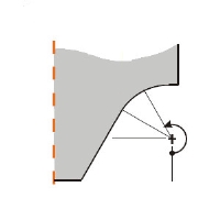
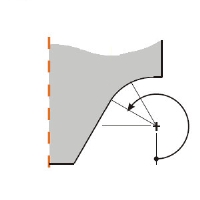
- Start Angle - The point on the radius in relation to its center at which profile checking begins.
- End Angle - The angle, in relation to the start angle, at which the radius of the cutter terminates.


Quick Steps - Radius Profile Checking
- In the CAM Tree, right-click Milling Tools, and select Tool Crib.
The Tool Crib dialog launches in the Data Entry Manager. - Add all tools needed for the job.
- Click OK.
The Tool Crib dialog closes. - In the CAM Tree, locate the desired Machine Setup for the Probing cycle, right-click the Machine Setup, and select Probing.
The Probing dialog launches in the Data Entry Manager. - In the Machining Strategy list of the Feature page, click the Non-Contact Tool Setter operation.
The Non-Contact Tool Setter operation replaces the Measure operation in Current Operations list. - Click the Operations(s) tab.
- Select the appropriate cycle from the drop down list in the Cycle section of the Parameters tab.
- In the Parameter section, select the tool and adjust the select the Override Tool Data check box is necessary.
If you select the Override Tool Data check box, adjust the Tool Number and Tool Diameter values as needed. - In the Options section, select the check boxes for any and all calls required in the output and set their values as needed.
- Select the Raw Text tab in order to output any macros or code manually.
- In the Raw Text tab, select the Output in NC Program check box.
- Enter the data to be output in the text field.
- Click OK.
The operation is added to the CAM Tree.
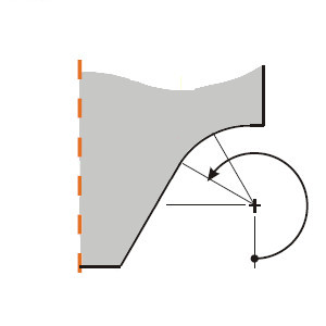
Example - Radius Profile Checking (Negative Radius)
The Radius Profile Checking cycle is designed to verify the shape of the tool is still true to the specification.Because of this, exact figures must be known so they can be entered accurately in the option values of the cycle. Having a drawing of the tool profile to check the proper values is extremely helpful for this cycle. It is also important to know which value to use for the described radius.While using a positive radius will describe a radius as is found in a ball endmill, using a negative value will describe a concave radius as found in a corner round tool.In this case we will be describing a negative radius.
In this example we:
- Setup the Tool Crib.
- Select the Tool Diameter cycle.
- Select the tool.
- Set the Linear Distance.
- Set the Options.
Part 1) Setting up the Tool Crib
- In the CAM Tree, right-click Milling Tools, and select Tool Crib.
The Tool Crib dialog launches in the Data Entry Manager. - Add all tools needed for the job.
- Click OK.
The Tool Crib dialog closes.
Part 2) Selecting the Radius Profile Checking cycle
- In the CAM Tree, locate the desired Machine Setup for the Probing cycle, right-click the Machine Setup, and select Probing.
The Probing dialog launches in the Data Entry Manager. - In the Machining Strategy list of the Feature page, click the Non-Contact Tool Setter operation.
The Non-Contact Tool Setter operation replaces the Measure operation in Current Operations list. - Click the Operations(s) tab.
By default the Tool Length is the selected cycle.
- Click the drop down and select Radius Profile Checking from the list.
Part 3) Selecting the Tool to be checked and its radius
- In the Parameters section, select the tool to be set from the drop down list.
By default the Tool Offset is set to the tool number of the selected tool. - Select the Override Tool Data check box.
- Set the Tool Diameter value to the radius being checked.
Since our tool has a concave radius, we use a negative value.
Part 4) Setting the Linear Distance
- In the Linear Distance text box, set the distance to be measured past the radius of the tool.
Part 5) Setting the Options
- In the Options section, select the check box for Radial Distance.
- In the Radial Distance text box, set the distance from the radius center to the spindle axis.
- In the Options section, select the check box for Check Height.
- In the Check Height text box, set the distance from the radius center to the tool tip.
- In the Options section, select the check box for Start Angle.
- In the Start Angle text box, set the angle to begin measurement of the described radius.
- In the Options section, select the check box for End Angle.
- In the End Angle text box, set the angle at which the radius terminates.
- Click OK to create the Radius Profile Checking cycle and exit the dialog.
Tip: To learn about how to use the Broken Tool Flag option, see the examples in the Broken Tool - Plunge and/or Broken Tool - Solid topics.