The Status Bar
Introduction
This topic will provide details on the various aspects of the Status Bar.
The Status Bar
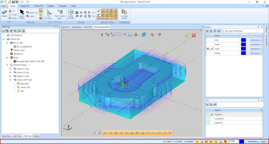
The Status Bar, shown highlighted in red in the image below, is at the bottom of the user interface, and displays information about the current state of the software. The status bar can be viewed as two main items, the Prompt Line and the Status Bar.
The Prompt Line
The left side of the status bar contains the prompt line.
| For Help, press F1 |
When you open a CAD function, the prompt line displays information to help guide you through the steps of performing the function.
| Click end of first chain entity, or hold Shift and click the end of chain. |
The Status Bar
The right side of the status bar displays various active settings for the system as explained next.

From left to right, the status bar contains the following:
- X/Y/Z Indicators
The X, Y, and Z values display the current location of the mouse pointer in the graphics area. -
 Show/Hide X-Y Axis and Gnomon - Turns on/off the Axis and Gnomon displays. These can be controlled individually in Axis X -Y group of the Display page found in the Document Default and Current Document tabs of the Settings dialog.
 - X-Y Axis and Gnomon On:
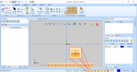
- X-Y Axis and Gnomon Off:
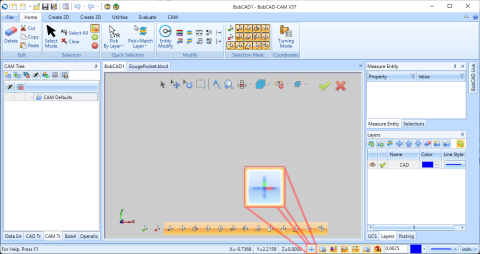
- X-Y Axis and Gnomon On:
-
 Enable/Disable Contextual Help - allows users to hover over an item to see a definition and get a link to the associated help topic when one is available. Currently many of the CAD items have contextual help information associated with them.
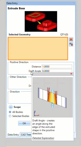
-
 Enable/Disable Contextual Toolbar
The Enable/Disable Contextual Toolbar button allows you to utilize the available contextual toolbars, rather than just the context menu, for selection of functions.- Context Menu :
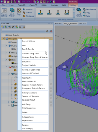
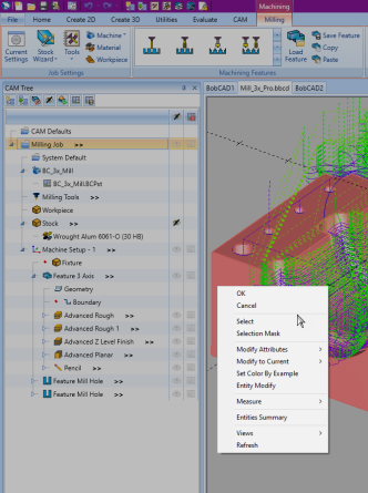
The Context Menu is accessible in all CAM related trees, as well as the graphics area. Simply right-click an item to view the available options through the context menu. This is possible whether or not the Contextual Toolbar button is toggled on. - Contextual Toolbar :
The Contextual Toolbars offer you the most commonly used options in a more simplified form. With the Enable/Disable Contextual Toolbar Button toggled on, simply left-click the item to view the available options in a simplified toolbar.
- Context Menu :
-
 Views to Active UCS
The Views to Active UCS button allows you to force the view options to be relative to the active UCS.- View to Active UCS: Off
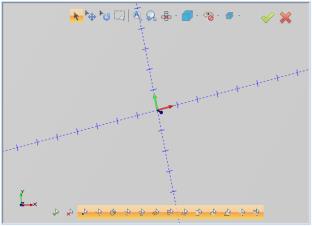
When working in a User Coordinate System (UCS) that is askew from the World Coordinate System (WCS), moving into a top view sets the view based on the WCS. Notice how the WCS gnomon in the lower left of the graphics area is oriented in the top view, while our axis and UCS gnomon remain askew. - View to Active UCS: On
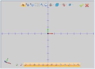
When working in a User Coordinate System (UCS) that is askew from the World Coordinate System (WCS), and with the View to Active UCS toggle on, the view is based on the UCS. Notice how the WCS gnomon in the lower left of the graphics area is askew, while our axis and UCS gnomon is oriented in the top view.
- View to Active UCS: Off
-
 Construction Geometry and X_Y Tracking
The Construction Geometry and X_Y Tracking button displays helpful points and reference lines to aid in CAD design.- Horizontal and Vertical references - while drawing, the construction geometry will display possible straight lines in reference to the X/Y directions, as well as perpendicular and parallel directions from the currently selected geometry.
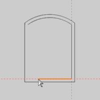
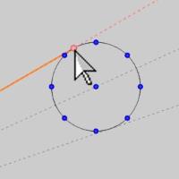
- Tangent points - while drawing, the construction geometry can display the tangency point on arcs.
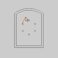
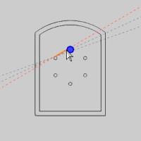
- X/Y Tracking - while drawing, the construction geometry can display possible points of interest when the position is in line with items in the X and Y directions.
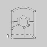
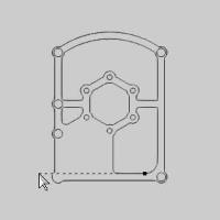
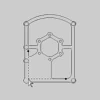
- Horizontal and Vertical references - while drawing, the construction geometry will display possible straight lines in reference to the X/Y directions, as well as perpendicular and parallel directions from the currently selected geometry.
-
 CAM Tree Flyouts
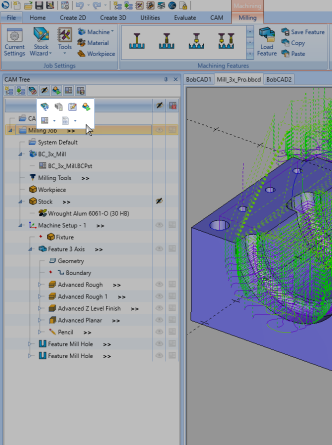
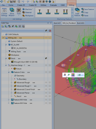
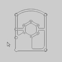
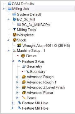
The CAM Flyouts are designed to do two things. First, they provide a way to quickly view information you may be looking for easily. Secondly, they provide a way to edit some values without the need to open a dialog and search for them in that dialog. The CAM Flyouts can be toggled with this icon, or by selecting/deselecting the Enable CAM Tree Flyouts check box in the settings dialog. When the toggle is on, as they are in the lower left image, certain items in the CAM Tree will be shown with >> to the right of them. These are the items that offer a flyout. Simply hover over the >> to view the flyout. Then click elsewhere to close the flyout. Turning the Flyouts off will remove them from the CAM Tree, as shown in the image on the lower right.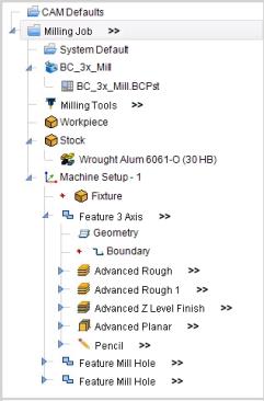
-
 Enable/Disable Snap
The snap increment button allows you to quickly turn on and off the snap increment for drawing (you can also press the shortcut key Q). The snap increment distance value can be updated in the status bar by typing a new value and pressing Enter. - Active Color Selector
To the right of the XYZ indicators is the Active Color Selector. This box displays the current color that is used for creating wireframe entities. To change the active color, click the arrow and select the new color.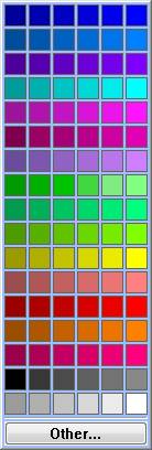
- Line Style Selector
To the right of the active color selector is the Line Style Selector. This displays the current line style that is used for creating wireframe entities. To change the currently selected line style, click the arrow and select a new line style.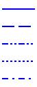
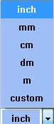
- Unit Type Indicator
The far right side of the status bar displays the selected unit type for the current file. To change the currently active unit type, click the arrow and select a new unit type.