What's New in BobCAD-CAM V37
Introduction
Welcome to the sneak peek of BobCAD-CAM V37! We're thrilled to unveil a host of exciting new features designed to streamline your part programming process and boost your efficiency. Our team has been hard at work incorporating user feedback to deliver a more intuitive and powerful experience. Whether it's the revamped context menu, enhanced tool management, or advanced machining options, V37 is packed with updates that cater to your needs. Dive in and discover how these new tools and improvements can elevate your workflow to new heights!
General Features
Automatically Utilize High Performance GPU
In BobCAD-CAM V37, the software now automatically leverages the High-Performance GPU on your computer, saving you from manually configuring graphic settings. This enhancement ensures that complex computational tasks are processed more efficiently, leading to faster performance and smoother operation. Especially beneficial for those unaware of manual configuration processes, this feature provides a significant performance boost without any extra steps, enhancing your workflow effortlessly.
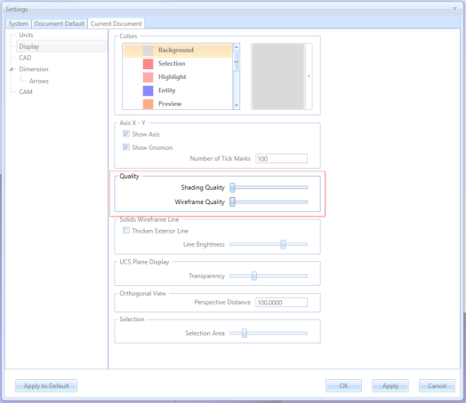
Default Shading/Wireframe Quality Increased
We've updated the default settings for visual quality to offer a cleaner, more refined look. Previously, default settings were kept low to minimize software stress. However, with modern computers' increased power and our ability to utilize high-performance graphics cards automatically, we've improved the default visual settings. This ensures users experience higher-quality visuals without compromising performance, fully capitalizing on current hardware capabilities.
|
|
|
|
LUA Plugin
In BobCAD-CAM V37 we're enabling the LUA registry keys by default! The LUA plug-in in BobCAD-CAM allows users to extend and customize the software's functionality through scripting. With LUA, customers can:
-
Automate Tasks: Create scripts to automate repetitive operations, saving time and reducing errors.
-
Enhance Post-Processing: Customize post-processor outputs for specific machine requirements.
-
Customize Interface: Modify and extend the user interface to better fit workflow needs.
-
Develop Custom Tools: Create new tools and functions to enhance machining processes.
These capabilities provide significant flexibility and efficiency for advanced users. For more details, visit the BobCAD LUA API help system.
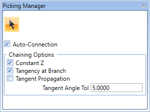
Remember Picking State
In response to user feedback, BobCAD-CAM V37 now retains the state of the Picking Manager even after closing and reopening the software. Previously, the Picking Manager would default back to Auto-Connection being enabled when the software was restarted. This update ensures that your preference for the Auto-Connection setting is preserved across sessions, offering a more consistent and user-friendly experience.
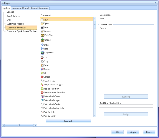
Customize Shortcuts Improvements
Shortcuts Alphabetized
In BobCAD-CAM V37, we have improved the Customize Shortcuts dialog by alphabetizing the functions. This enhancement allows users to find and assign shortcuts to functions more easily, streamlining the customization process. By organizing the functions alphabetically, users can quickly locate specific commands, improving efficiency and user experience.
| Before | After |
|
|
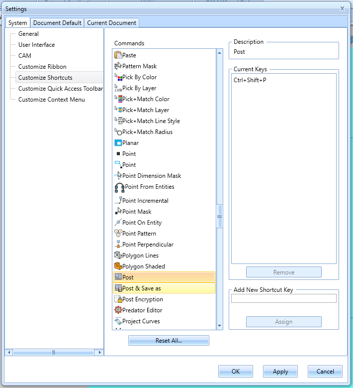
New Commands Available
New commands have been added to the Customize Shortcuts page of the Settings dialog. Post, Post & Save As, Start Simulation, Generate Setup Sheet, and Toolpath Statistics, all can have custom shortcuts created for them to make things just a little quicker for you!
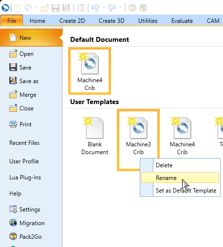
Renaming User Templates
Users can now rename their saved templates in the Backstage of the software. Previously, template names were permanent once saved. This new feature adds flexibility by allowing users to update template names as needed, providing a more dynamic and user-friendly experience when setting up projects.
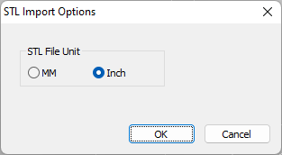
Open Options for STL
Importing STL models just got easier! When you drag an STL model into the software or open one from File > Open, a dialog box appears asking for the model's units. This feature eliminates manual scaling or changing default units, saving time and effort. If a file is already open, the dialog lets you choose to either open the STL on its own or merge it into your existing project, enhancing workflow efficiency.
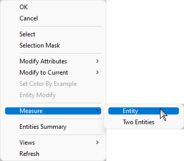
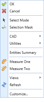
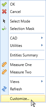
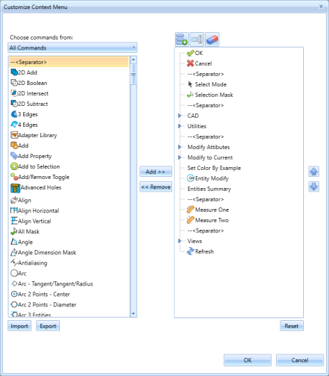
Updated Context Menu
In BobCAD-CAM V37, we've taken user requests to heart and revamped the context menu. A customer asked us to split the measure functions into individual options instead of accessing them through a single 'Measure' flyout. We did one better! Not only did we add those options by default, but we also introduced the Customize Context Menu dialog. Now, users can personalize their context menu to suit their needs perfectly. We’re not just meeting expectations; we’re exceeding them. Enjoy the ease and flexibility!
| Previous Context Menu | Current Context Menu | Simple Customization! | |
|
|
|
|
Automated License Deactivation During Uninstallation
We've improved the licensing process to help customers avoid common pitfalls. Previously, users often uninstalled the software without transferring the license, causing issues when trying to register it on a new computer. To address this, the uninstaller now automatically deauthorizes the license using the new install-bcl-deactivate.exe. This way the local license is deactivated upon uninstallation, eliminating the need to call technical support for license transfer issues!
BobART
Rename Sculpting Feature
Guess what? We've finally given you the ability to rename the Sculpting feature in BobART. We know, it’s about time! Now, instead of being stuck with "Sculpting_", you can personalize it to your heart's content. Whether it’s “Masterpiece #1” or “Happy Little Accident,” the choice is yours. Enjoy this new found freedom in BobCAD-CAM V37!
CAD Features
Tangent, Tangent, Radius
Introducing the new Tangent/Tangent/Radius circle function, which allows you to create circles using three entities, three points, or a mix of both, along with a specified radius. This versatile feature supports points, lines, arcs, and splines, making circle creation more flexible and precise. Start by generating a circle from three entities or points, then fine-tune it by entering a radius, and the algorithm recalculates accordingly. Enjoy this powerful new tool in BobCAD-CAM V37!
| First Entity | Second Entity | Estimate Size | Update Size Data as Needed |
|
|
|
|
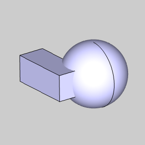
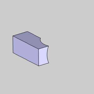
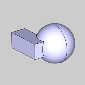
Keep Subtracted Body
By popular demand, the Boolean Subtract function now includes the option to "Keep subtracted geometry." This allows users to save the solid being subtracted, providing greater flexibility and control over their designs. No more losing valuable geometry—retain and reuse subtracted solids as needed. Enjoy this customer-requested enhancement to streamline your workflow!
| Sphere to be Deleted | ||
|
|
|
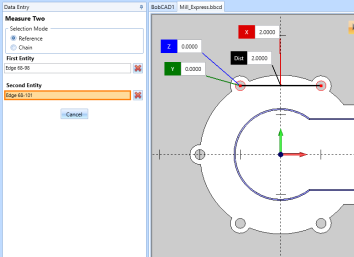
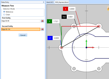
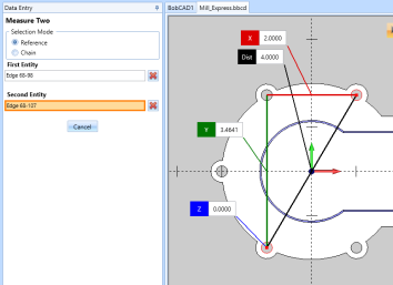
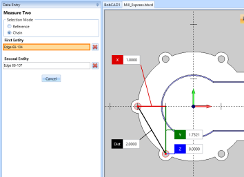
Updated Measure Two Flow
We've enhanced our Measure Two function based on your feedback. Previously, clicking a third entity would measure it against the first selected entity. To measure two new entities, you'd have to update the first entity in the Data Entry Manager. Now, Measure Two has two Selection Mode options:
-
Reference: Works like before, each new click measures against the first entity.
-
Chain: Measures two selected entities, then measures each new entity against the last selected one.
This update simplifies measuring multiple entities efficiently!
| Second Entity Selected | Third Entity Selected | Fourth Entity Selected | |
| Reference |
|
|
|
| Chain |
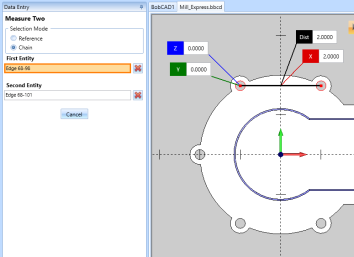
|
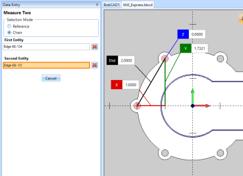
|
|
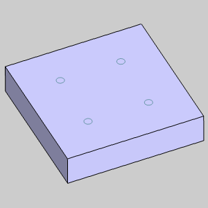
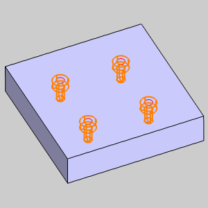
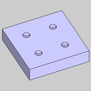
Advanced Holes Arc Selection
Based on customer feedback, we've updated the Advanced Hole feature to allow arc selection. Now, you can select an arc, and the feature will use the arc's center, making the process more intuitive and user-friendly. This enhancement aims to streamline your workflow and reduce confusion.
|
|
|
Rotate from Geometry Center
The new Rotate from Geometry Center feature allows you to set the rotation center for selected geometry at its center of mass. This enhancement ensures more accurate and intuitive rotations, particularly for complex shapes, by automatically determining the optimal center point. Enjoy precise and efficient rotations with this powerful new tool in BobCAD-CAM V37!
| Entities in Fixture to be Rotated | Default Rotation Center | Rotating from Geometry Center | Done |

|

|
|
|
Contextual Help
In BobCAD-CAM V37, we've added contextual help for CAD functions. Hover over an item to see a definition and get a link to the associated help topic. This feature provides quick access to information, making it easier to understand and utilize CAD functions effectively. Users can enable or disable this feature in the User Interface page of the Settings dialog, offering flexibility to tailor the interface to their preferences.
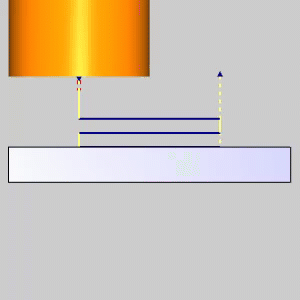
Views to Active UCS by Default
In the latest version of BobCAD-CAM, the Views to Active UCS feature, which sets the views (top, side, etc.) normal to the active UCS, is now enabled by default. This change aligns with user expectations, as most people assume views should automatically orient based on the active UCS. By making this the default setting, enhances usability and ensures a more intuitive experience for all users.
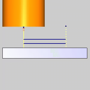
| View to Active UCS: Off | ||
|
||
| View to Active UCS: On | ||
|
Offset Both Sides
The new Both Sides Offset option allows you to offset a centerline to both sides simultaneously. Previously, this required two separate steps, which could be time-consuming. Now, you can perform this action in a single step, streamlining your drawing process and saving valuable time.
| Geometry to be Offset | Left | Right | Both Sides |

|

|

|

|
Reset Button for Move Functions
The new Reset Button for Move Functions allows you to easily reset values in move functions like Translate and Rotate. Previously, after performing a move operation, users had to manually reset values. With the Reset Button, you can instantly revert all values to their default settings, simplifying the application of move functions to new geometry and improving efficiency.
| Translating Entity | Click Reset to Clear Values | Values back to Default |
|
|
|
Cleanup tiny entities
The new Cleanup Tiny Entities option eliminates entities below a certain size to help clean up your files. Previously, functions like Cleanup/Optimize, Make Arcs Tangential, and Fit Arcs helped reduce these tiny entities, but unwanted remnants often caused workflow disruptions. Now, a new utility function automatically deletes any entity below a certain size and attempts to mend gaps in the chain, making it particularly beneficial for sign makers and BobART users who vectorize images and text.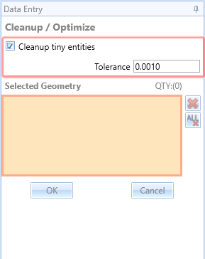
Axis & Gnomon Display Toggle
We've added a new button to the status bar to toggle the gnomon and axis crosshair display in the graphics area. Previously, these options could only be toggled through the current settings. Now, with these display options available directly on the main software screen, users can easily and quickly adjust their view, enhancing their overall user experience.
| On | Off |
|
|
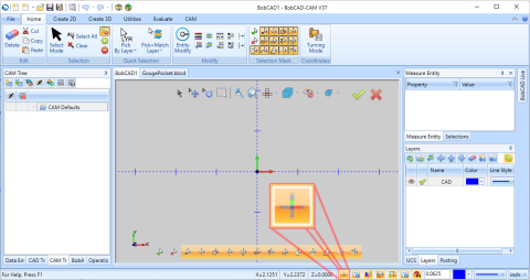
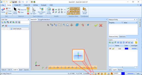
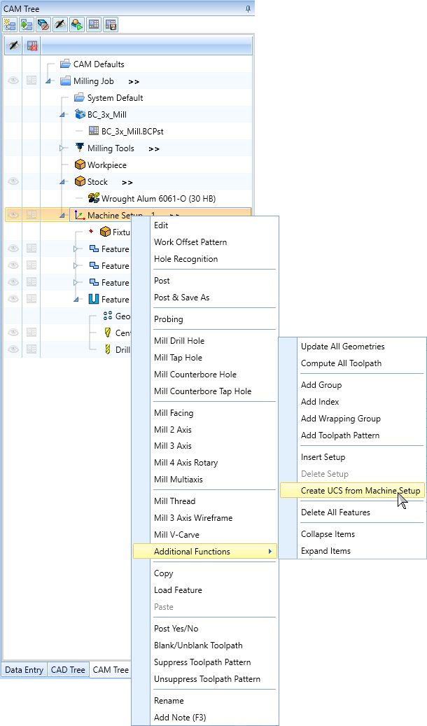
Create UCS Based on Machine Setup
We've introduced an option to create a User Coordinate System (UCS) based on a machine setup. This feature is particularly useful for importing parts that aren't aligned to a standard UCS, allowing users to develop geometry for boundaries that aid in the machining process. By simplifying the workflow, users can now more easily create and manage UCS for improved efficiency and accuracy.
Layer Deletion Update
In BobCAD-CAM V37, layers containing only hidden entities used by the CAD history tree can now be deleted. The hidden entities will be moved based on the following logic:
-
If the active layer is not marked for deletion, entities will move to the active layer.
-
If the active layer is also being deleted, entities will move to the first available layer, provided there are remaining layers.
CAM Features
General
Tool Library Improvements
Multiple Tool Libraries
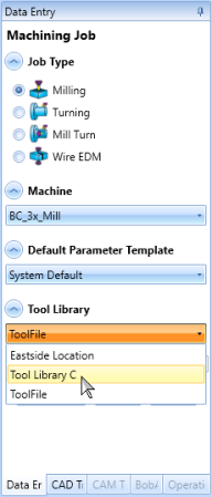
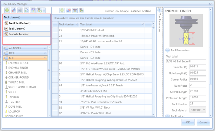
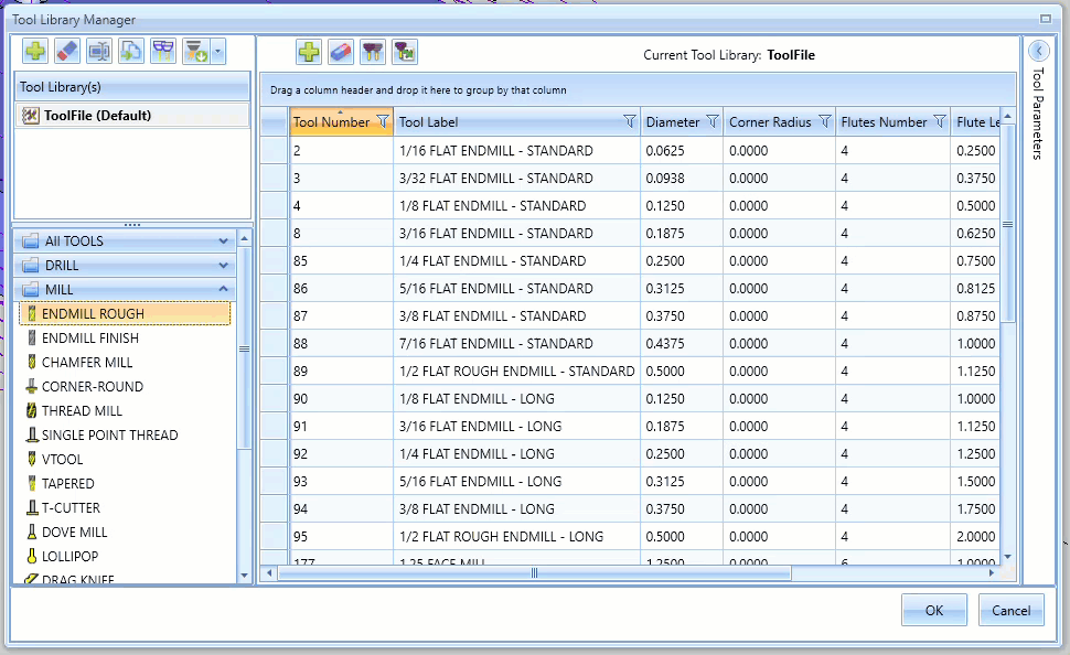
BobCAD-CAM V37 introduces the highly requested feature of Multiple Tool Libraries, addressing the challenges of using a single library. Previously, users faced difficulties managing tools across different machines, manufacturer-specific tools, and various shop locations. Now, you can easily separate tools by machine, manufacturer, or location. Additionally, new tools for managing multiple libraries include options for importing and merging libraries, cloning tools, and copying tools to other libraries. These enhancements provide greater flexibility, organization, and efficiency in tool management, tailored to your specific needs.
| Library Selection During Job Creation | Manage All Libraries in the Tool Library Manager | |
|
|
|
Tool Library Work Flow Update
In BobCAD-CAM V37, the tool creation workflow in the Tool Library has been significantly enhanced for user-friendliness. The create, delete, copy tools to library, and clone options have been moved to their own toolbar in the grid view of the tool library. Now, when a user clicks "Create Tool," the focus automatically scrolls to the new tool's location in the grid view, and the Tool Parameters flyout opens immediately for editing. This eliminates confusion for new users, who may not notice that a tool has been created, and saves time by removing the need to manually open Tool Parameters and scroll to the new tool's position. This update simplifies the process, making it more intuitive and efficient for users to create and manage tools.
Warning to Save Tool Library
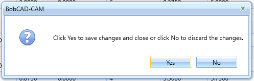
In BobCAD-CAM V37, we've introduced a useful feature for those moments when you hit "x" instead of "OK" after modifying a tool in the library. First, we've replaced the 'x' button with a Maximize/Restore button to prevent accidental closure, but if you still manage to close without saving, a prompt will now appear: "Click Yes to save changes and close or click No to discard the changes," with Yes/No options. This ensures your changes are saved and spares you from redoing your work. You're welcome!
Tool Crib Improvements
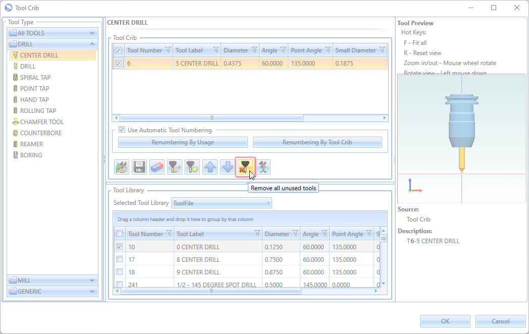
Remove Unused Tools
A new button allows users to automatically remove all unused tools from the Tool Crib. Previously, this task required manual verification and deletion, which was tedious. With this new feature, a simple click is all that's needed to eliminate any and all unused tools. You can't get much easier than that!
Remember Tool Crib Size
BobCAD-CAM V37 now retains the previous window size and position of the tool crib, addressing a common issue for users with specific screen configurations. Previously, users had to resize the tool crib window each time it was opened, as the software did not remember the last used dimensions. This enhancement keeps it nice and convenient by keeping the tool crib window at the preferred size and position every time it is accessed.
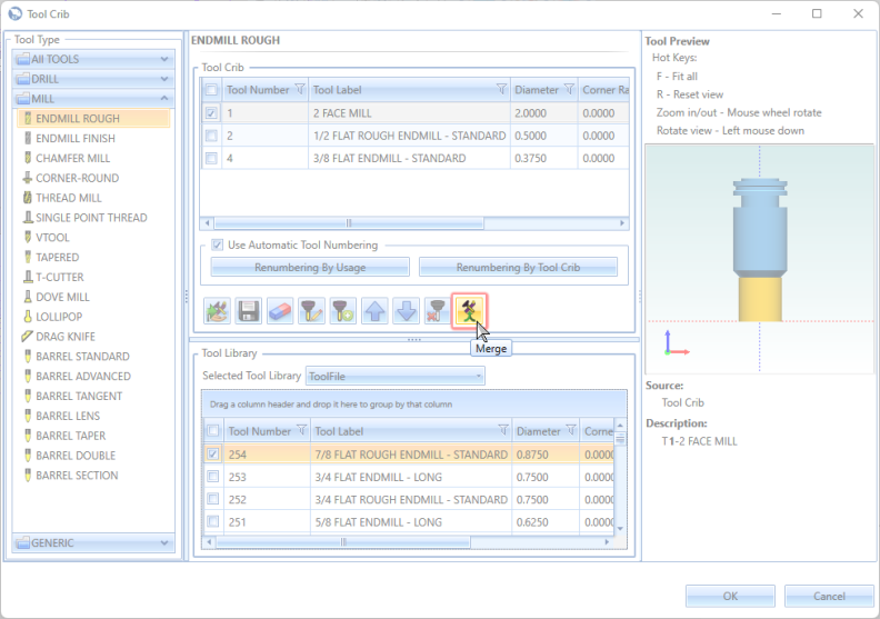
Merge Options for Tool Crib Import
The new Merge Tool Crib option in BobCAD-CAM V37 makes tool management a breeze by letting you merge a saved tool crib with your current one. Before, importing a tool crib meant losing your existing setup, which was a hassle since you'd have to re-add your tools manually, risking mistakes. Now, you can easily combine your tool cribs, keeping everything you need in one place without the extra work.
Updated Tool Crib Selection
In BobCAD-CAM V37, we've addressed customer frustration with tool selection in the Tool Crib. Previously, if a tool wasn't dragged from the Tool Library section, up to the Tool Crib section, the software would continue to use the previously active tool in the Tool Crib. Now, when a tool in the Tool Library is the last item the user click on, a prompt will appear: "Last selected tool(s) were in the Tool Library. Would you like the tool(s) added to the Tool Crib? If multiple tools have been selected, the first selected tool will be applied to the operation."
*While the proper method is to move tools to the actual Tool Crib, this ensures users won't incorrectly assume they have done so.
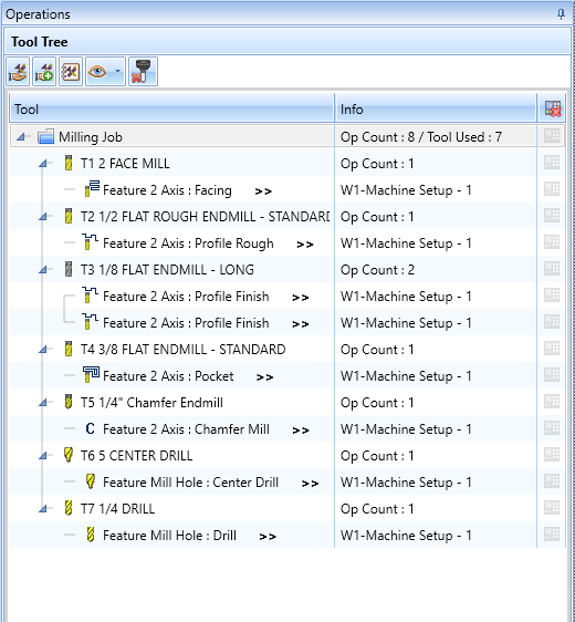
Show Tool Count in Tool Tree
BobCAD-CAM V37 now features a new display in the Tool Tree's Info column, showing the number of tools used in the job next to the number of operations. This makes it easy to verify the tool count at a glance. In the past, users couldn't see the total tool count, which made verification more tedious. This enhancement provides a quick and efficient way to check the number of tools in use while reviewing operations.
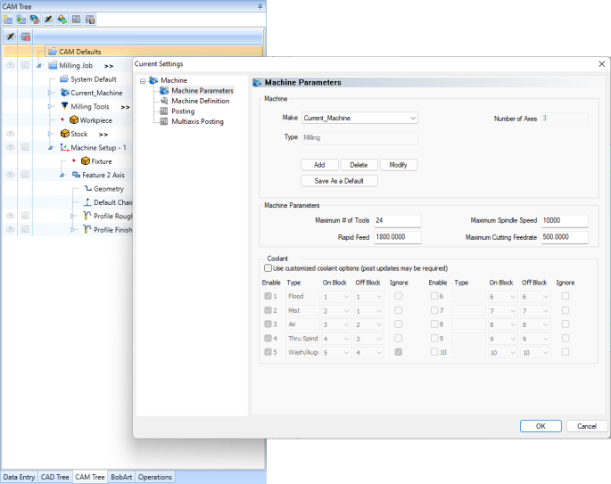
Default to Last Used Machine
In BobCAD-CAM V37, the Current Settings dialog has been improved for better user-friendliness. Previously, launching this dialog from the "CAM Default" item or the CAM ribbon always defaulted to the BC_3x_Mill machine. Now, the software will use the machine from the last visited job, making it easier to edit or view parameters relevant to the current active job. If no item has been selected in the CAM tree, the machine from the first job in the tree will be used.
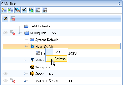
Machine Refresh Button
We're also adding a more intuitive way to refresh the machine being used for the job. Previously, when a machine was changed in the job users had to right-click on the Machine in the CAM Tree, select Edit, and click OK to refresh the machine being shown in simulation. Now, a "Refresh" button is added to the right-click menu, allowing users to update machine changes in the current job a little quicker. Additionally, when changes are made in the CAM Defaults > Current Settings, a prompt will appear asking, "Do you want to apply these machine changes to your current job?" Clicking "Yes" will automatically refresh the current job's machine settings.
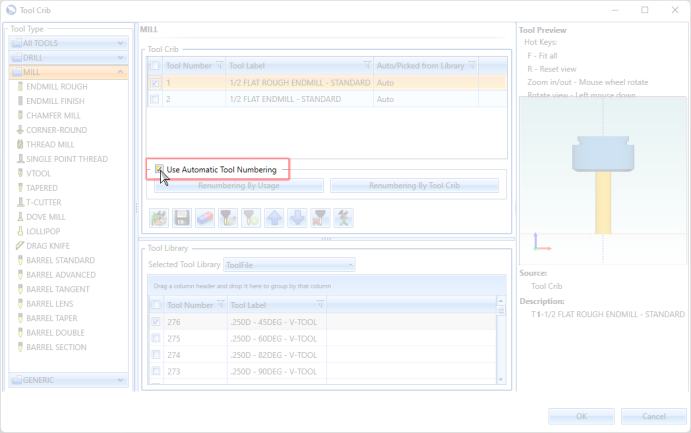
Save Use Automatic Tool Numbering to Job Template
A new enhancement allows the Use Automatic Tool Numbering checkbox to be stored in Job Templates. Previously, this option was always checked by default, even if it was unchecked when the template was saved. This required users to manually adjust the tool number before posting the code. With this update, the checkbox state will be saved in the Job Template, allowing it to be disabled by default when loading new templates, streamlining the workflow and reducing the need for manual adjustments.
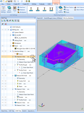
Remove Highlight from Geometry
The "Remove Highlight from Geometry" update in BobCAD-CAM V37 enhances the way feature geometry is highlighted. Previously, when you clicked on a feature in the CAM Tree, the corresponding geometry would highlight in the graphics area, helping you identify specific features among many. However, the highlight would remain until another feature was selected or the Job was clicked in the CAM Tree, which could be inconvenient. With this update, you can now remove the highlight simply by clicking anywhere, including empty space in the graphics area, making the workflow smoother and less distracting.
| Find Feature to Highlight | Click to Highlight | Click Elsewhere to Remove Highlight |
|
|
|
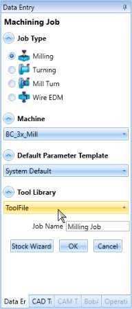
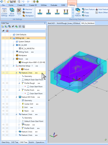
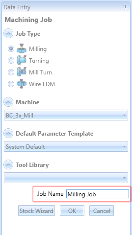
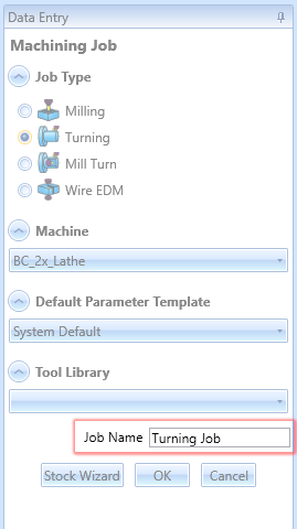
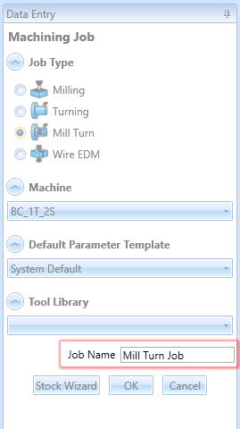
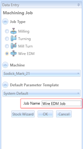
Add Job Name at Creation
You now have the ability to update the Job Name directly in the Data Entry Manager during job creation. Previously, while it was possible to change the Job Name in the CAM Tree after the job was created, there was no option to set or modify the name during the initial setup. This enhancement streamlines the process, allowing you to assign a meaningful and specific name to your job right from the start, improving organization and efficiency in your workflow.
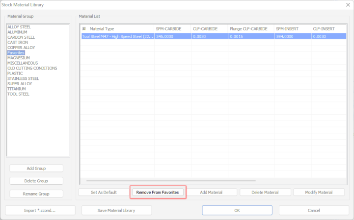
Remove From Favorites
In BobCAD-CAM V37, managing the "Favorites" group in the material library has been improved. Previously, users could easily move materials to "Favorites" but had no simple way to remove them. Now, when in the "Favorites" tab, the "Move to Favorites" button is replaced with "Remove from Favorites." Clicking this button will move the selected material back to its original group. If the original group no longer exists, a dialog box will prompt the user to select a new group from a list of current groups.
Mill
Mill Express
General
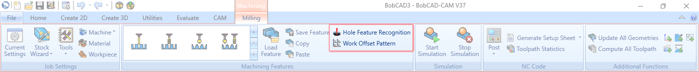
Work Offset Pattern and Hole Recognition added to CAM Ribbon
In BobCAD-CAM V37, we've made it easier to access important features by adding Work Offset Pattern and Hole Recognition buttons to the CAM Ribbon. Previously, accessing the Work Offset Pattern required navigating through the Machine Setup in the CAM Tree, which many users were unaware of. By placing these options directly in the ribbon bar, we've made these powerful features more visible and accessible. This change ensures that even users who were previously unaware of these capabilities can easily find and utilize them, enhancing their overall experience and efficiency.
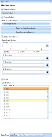
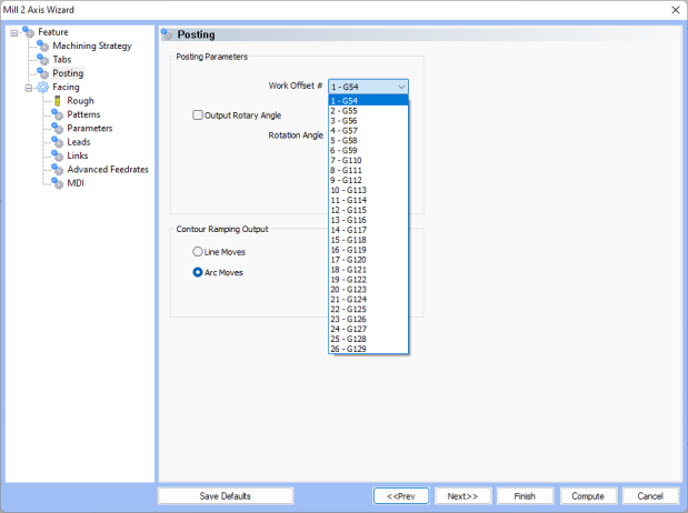
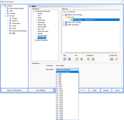
Work Offset String Values
In BobCAD-CAM V37, work offset numbers have been enhanced by displaying their string values as assigned in the post processor. Previously, work offset numbers were listed sequentially, which did not reflect their actual values in the output. Now, with the string values displayed, each job will show the exact work offset value as it will appear in the output, ensuring accuracy and consistency in the machining process.
| Machine Setup | Posting Page | MDI Page |
|
|
|
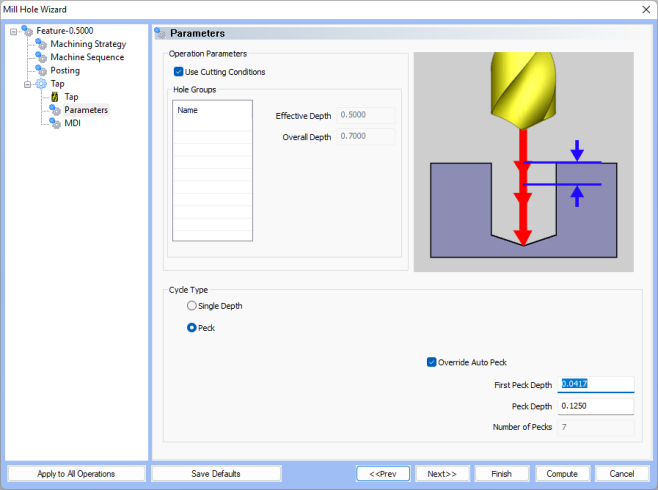
Pecking in Tap Operations
In BobCAD-CAM V37, we've enhanced the peck tapping cycle to include support for multiple machines such as Fanuc, Siemens, Heidenhain, and Haas. Previously, a custom script was required to achieve this functionality. Now, it's built into the posting engine, eliminating the need for scripting. This update allows users to add peck depth in tapping cycles seamlessly. For Haas machines, specific blocks (102 & 103) have been introduced to handle the unique peck tapping format, ensuring compatibility and ease of use across different machine types.
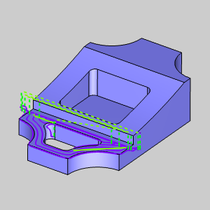
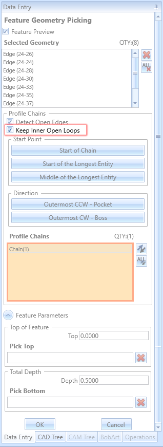
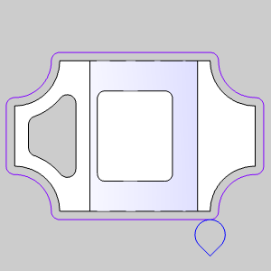
Keep Inner Open Loops
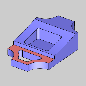
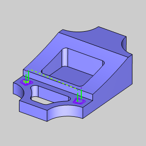
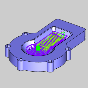
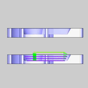
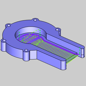
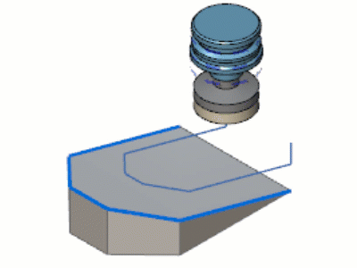
The new Keep Inner Open Loops feature in BobCAD-CAM V37 improves the Detect Open Edges option by providing users with greater control over unwanted chains. Previously, using Detect Open Edges could include elements like through holes, which disrupted toolpath creation. Addressing these issues often required extra work, so we've introduced the Keep Inner Open Loops option. By default, inner open loops will be ignored, but if you need them, simply enable the Keep Inner Open Loops feature! In the images below, based on the geometry we selected, you can see it's pretty obvious we're going to want to detect open edges, but do we want to keep our open inner loops? If the through pocket hasn't been machine, we would not want to keep the inner loops. However, if the through pocket has been machined, we'd want to select Keep Inner Open Loops. With these available options you're ready for either situation without needing additional geometry!
| Geometry Selected |
|
|
|
|
|
|
|
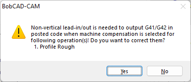
Machine Compensation Warning
We've improved the handling of machine compensation (G41/G42) in scenarios where a vertical lead-in/lead-out is used. Some users were unaware that machine compensation cannot be applied with vertical lead-ins/lead-outs, which lead to confusion when G41/G42 codes were missing from the output. To address this, a message will now be displayed when you finish, compute, or post an operation attempting to use machine compensation with a vertical lead-in/lead-out. This ensures users are immediately informed and can make the necessary adjustments, enhancing clarity and reducing errors in the coding process.
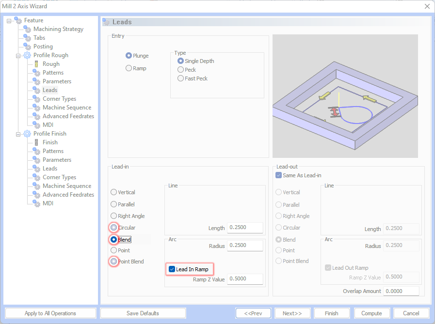
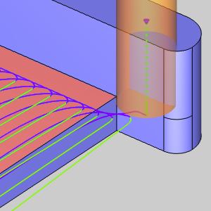
Lead-in / Lead-out Ramp
In BobCAD-CAM V37, we've introduced a ramp option for lead-in and lead-out options that include arcs in the output. This addresses a client request for improved workflow in CNC router programming. Previously, users had to manually edit the code by adding Z values to create ramping, which could be pretty time-consuming and even prone to errors. This new feature automates the process, eliminating the need for manual code adjustments and preventing material burns caused by motion pauses.
Important to note:
-
The lead-in line entity handles compensation, so ramping on line entities is not possible.
-
Ramping can only be applied to arc entities. Therefore, the ramp option will only be visible for Circular, Blend, and point blend lead-in/lead-out types.
This enhancement streamlines programming and ensures smoother transitions, significantly improving the efficiency and precision of CNC router operations.
| Top View Ramp on Point Blend Lead |
Side View Ramp on Point Blend Lead |
|
|
Mill Holes
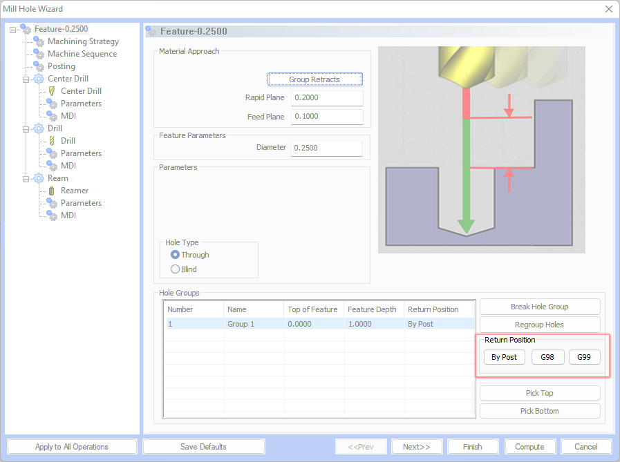
G98 / G99 Selection from CAM Wizard
In BobCAD-CAM V37, we've made it easier to control how your drilling operations are handled by adding the option to choose between G98, G99, or your post's default settings. This new feature ensures that your posted code and simulation match perfectly, providing better control and precision.
With this enhancement, you can select the appropriate retraction mode for each hole, either prioritizing speed with G99, which reduces cycle time, or safety with G98, which avoids obstacles by retracting to a higher position. This flexibility improves workflow by eliminating the need for manual adjustments and ensuring consistency across your operations. This update was requested multiple times and discussed extensively with the posting department, highlighting its importance for streamlining the drilling process and making it more efficient for users.
Laser, Plasma, Waterjet Jobs
Default Machining Strategy
In BobCAD-CAM V37, we've streamlined the workflow for users operating Plasma, Laser, and Waterjet machines by setting the system default in the Mill 2 Axis Feature to include only one Profile Finish operation. This change eliminates the unnecessary Profile Rough operation, which is rarely needed for these types of machines. While users can still create custom templates on the Machining Strategy page, this update ensures that when a Laser, Plasma, or Waterjet machine is selected, only the Profile Finish is shown by default on the Machining Strategy page. This adjustment minimizes extra clicks and makes the process more intuitive, particularly for new users.
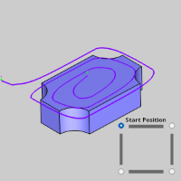
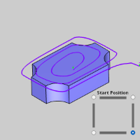
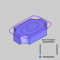
Facing
Start Position for Adaptive Patterns
In BobCAD-CAM V37, we've enhanced the Facing operation by allowing users to set the Start Point when using the Adaptive pattern. Previously, this functionality was available only for the Zig and Zig Zag patterns, enabling users to select one of four corner positions to start their toolpath. This flexibility ensures that users can choose the most ideal starting point for their needs. With this update, the same control is now available for the Adaptive pattern. If the default start position isn't suitable, users can easily switch to one of the three other corners, optimizing the toolpath start for better efficiency and results. This improvement provides greater control and customization, enhancing the overall user experience.
|
|

|
|
|
Minimize Retracts Enhancement
In BobCAD-CAM V37, the Minimize Retracts option for facing operations has been enhanced. While facing in one pass is not new, this enhancement ensures the tool not only avoids retracting but also moves directly to the next depth after the first pass. This improvement allows for continuous movement, increasing efficiency and reducing unnecessary tool travel, making your machining process smoother and faster.
| Old behavior | Updated behavior |
|
|
2 Axis Advanced Pocket
Tapered Pockets
By popular demand, BobCAD-CAM V37 now offers Tapered Pockets! The Parameters page of the Pocket operation features a new Taper/Draft Angle Option section. This addition allows you to set the desired angle for the pocket walls and choose whether the selected geometry for the feature is at the top or the bottom of the specified taper angle. This enhancement provides greater flexibility and control, enabling users to create tapered pockets with ease and precision, catering to a wider range of design needs.
| Designing the Taper | Resulting Model |
Tapered Pocket Toolpath! |
Side View |
|
|
|
|
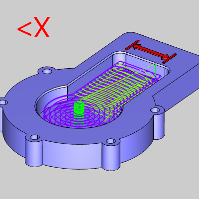
Gouge Check Curves
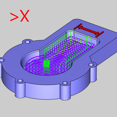
In BobCAD-CAM V37, a new Gouge Check Curves item appears in the CAM Tree for Pocket operations using the Adaptive Roughing pattern. This feature is crucial for open pockets with neighboring walls at the open end, preventing the tool from driving into these walls. Previously, users had to tweak pocket geometry to avoid collisions, leading to unnecessary toolpath. Now, simply select the curves to be avoided, and the toolpath will be updated, ensuring efficient and collision-free operations!
| Adaptive Roughing Pocket (Open) | Gouge on Neighboring Wall |
Selected Edge for Gouge Check Curves |
Updated Toolpath |
|
|
|
|
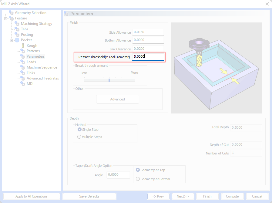
Retract Threshold
The new Retract Threshold allows you specify how long your link clearance moves are allowed to be before retracting to the rapid plane when using the adaptive pattern. Wasting moves on a retract when you know you could just keep the tool down is always frustrating and with this release we give you full control over how long your link clearance moves can be. Simply set the Link Clearance height, and set the retract distance as a multiple of your tool diameter and you're good to go!
| Retract Threshold (x Tool Diameter) |
Retract Threshold (x Tool Diameter) |
|
|
Sharp Corners
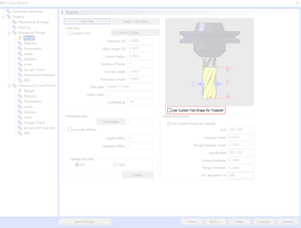
Users of the Advanced Pocket’s Offset patterns will be excited about the introduction of the Sharp Corners feature. This new development significantly enhances flexibility and precision in machining. The feature allows users to apply sharp cornering not only to open corners but also to all convex corners. This expanded capability dramatically broadens the range of design possibilities, enabling users to achieve more accurate and precise results. It's a considerable advancement for those seeking to produce sharp, defined corners, offering increased control and versatility in machining operations. This enhancement is particularly useful for complex geometries where sharp detailing is essential, marking a step forward in precision machining technology.
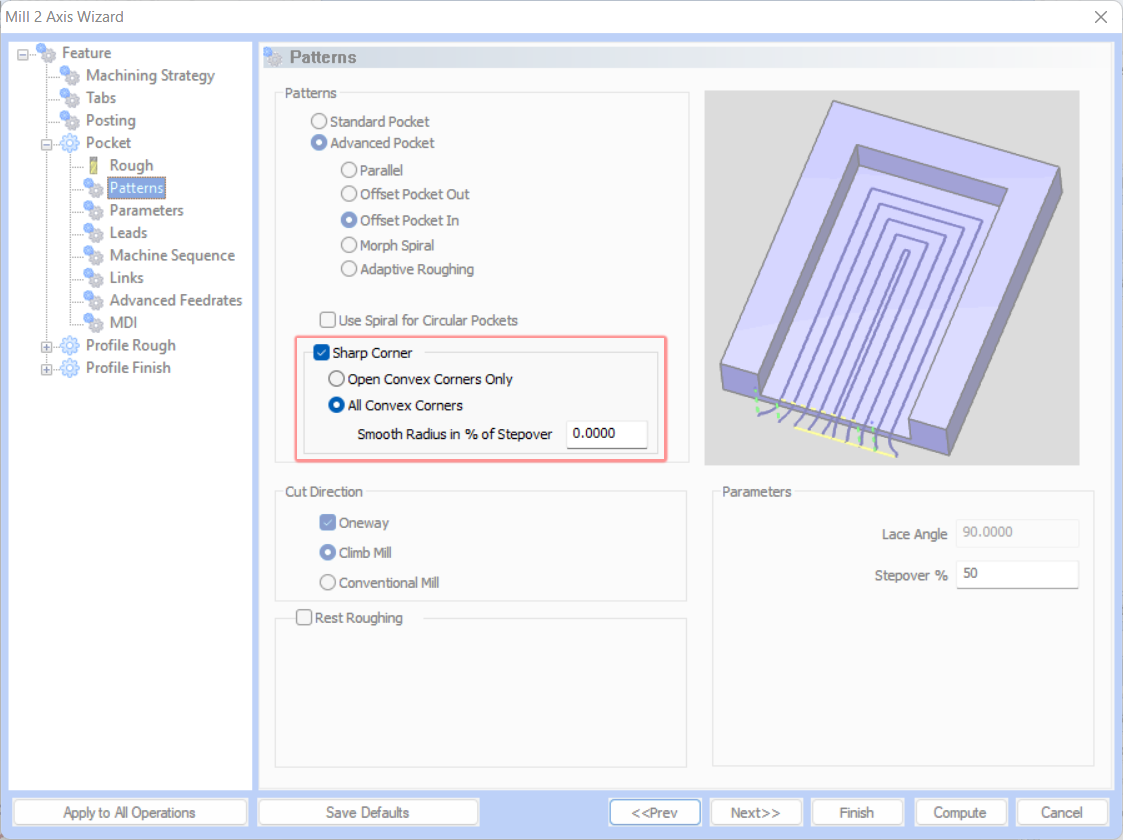
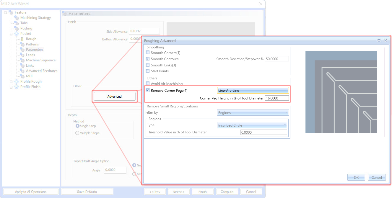
Smooth Peg Loops
In the Offset patterns of the Advanced Pocket operation, a significant refinement has been made to the Remove Corner Peg feature, particularly to its Line-Arc-Line option. This improvement ensures that the toolpath transitions at corners are smoother and more consistent, shifting away from abrupt changes to a linear path. As a result, this enhancement not only provides smoother toolpaths at these critical junctures but also considerably reduces the peak load on the cutting tool. This leads to more efficient cutting operations, decreasing the stress on tools and enhancing the overall quality of the machining process.

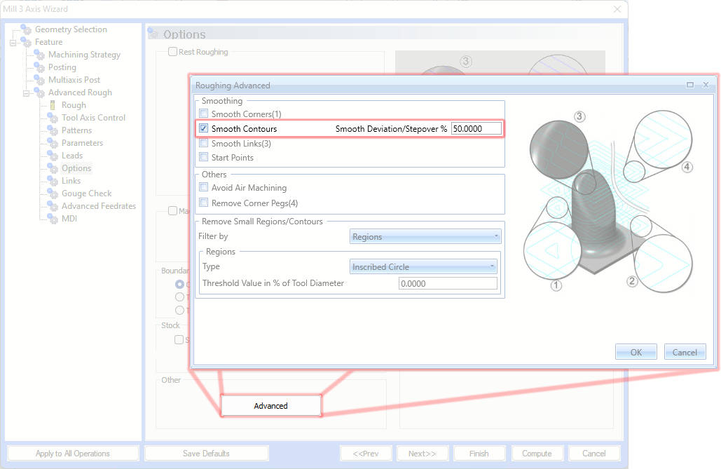
Smoothing Control for Offset Patterns
The Advanced Pocket operation has received a significant upgrade with the introduction of Smoothing Control for Offset Patterns. This improvement is particularly beneficial for intricate and detailed features, ensuring that offset patterns are seamlessly smoothed out. The key advantage of this refinement is the preservation of the original last contour while minimizing abrupt changes in acceleration and deceleration. This results in reduced jerking motions during machining, leading to constant, high-speed roughing. The outcome is a smoother operation overall and superior efficiency, making it a vital update for achieving high-quality finishes and precise machining.
Mill 3 Axis Pro
General
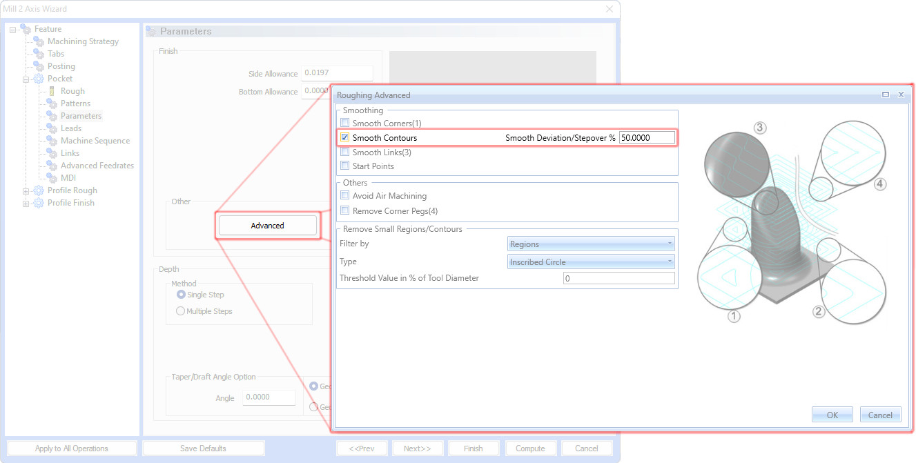
Use Custom Tool Shape for Toolpath
In BobCAD-CAM V37, there's a new option on the tool page allowing users to decide if a custom tool shape is used for toolpath calculation. This feature is available in Advanced Rough, Advanced Z Level Finish, Multiaxis Wireframe, and Surface-based operations. By selecting the "Use Custom Tool Shape for Toolpath" checkbox, the custom shape will be utilized during toolpath calculation. When unchecked, the tool will be defined using the parameters on the Tool Page. This provides greater flexibility and control over toolpath creation.
Advanced Rough
Smooth Peg Loops
In the Advanced Rough operation, a significant refinement has been made to the Remove Corner Peg feature, particularly to its Line-Arc-Line option. This improvement ensures that the toolpath transitions at corners are smoother and more consistent, shifting away from abrupt changes to a linear path. As a result, this enhancement not only provides smoother toolpaths at these critical junctures but also considerably reduces the peak load on the cutting tool. This leads to more efficient cutting operations, decreasing the stress on tools and enhancing the overall quality of the machining process.
Improved Peg Loops
The Advanced Rough operation has been further optimized through the improved integration of peg loop segments into offset contours. This refinement eliminates sudden shifts in machining direction, resulting in smoother and more consistent operations. This improvement not only enhances the quality of the machining process but also contributes to the longevity of the tools used. By providing smoother transitions and reducing abrupt changes, the operation ensures a more efficient and reliable machining experience, delivering superior results.

Reduce Number of Ramps
A notable optimization has been introduced to the Offset patterns in the Advanced Rough operation. This enhancement focuses on streamlining the machining process for intricate, nested toolpath contours by minimizing unnecessary retractions and ramps. The result is a dual benefit of reduced machining time and extended tool life. This optimization is a significant advancement, offering users increased efficiency and durability in their machining processes, ensuring a more cost-effective and time-efficient operation.

Avoid Small Profile Ramps
The Offset patterns in the Advanced Rough operation now feature a refined approach to creating Profile ramps. This enhancement strategically shifts smaller ramps to subsequent tool passes, effectively avoiding the creation of inefficient ramps near plunge moves. This optimization leads to improved tool cooling and more effective chip removal during the approach phase, ultimately extending the life of the tools. This advancement not only enhances performance but also contributes to the overall efficiency and longevity of the machining process.

Improved Stock Aware Linking
In an ongoing effort to refine efficiency, the Advanced Rough operation now features improved linking moves equipped with in-process stock recognition. This advancement means that the system not only checks against the part itself but also considers the in-process stock during linking motions. This development significantly reduces unnecessary link and ramp movements while ensuring a collision-free toolpath. The result is a smoother, more efficient machining process, marked by reduced time and increased precision.

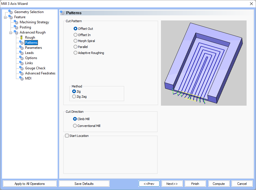
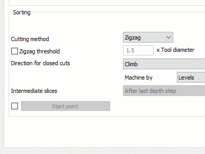
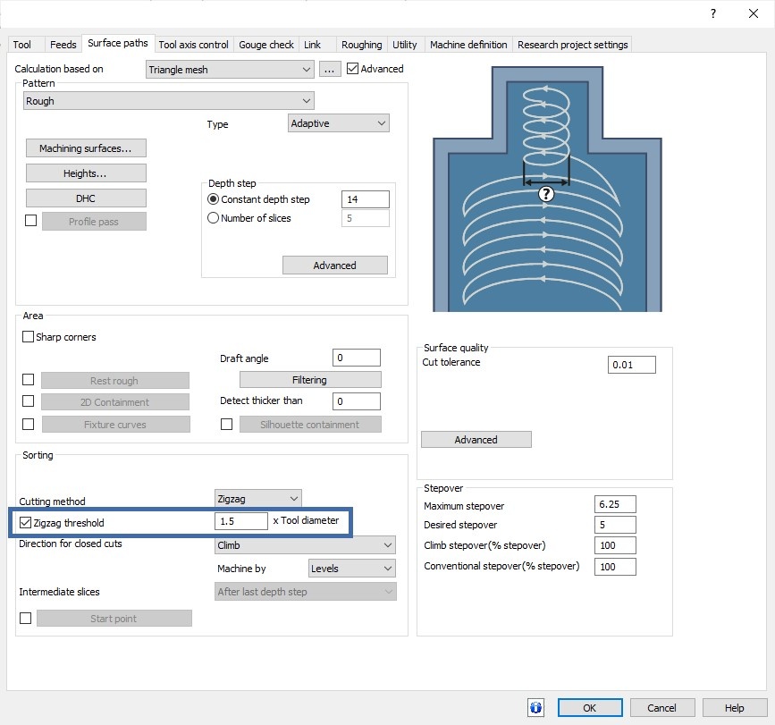
Zig-Zag Threshold
The Advanced Rough operation welcomes the new Zig-Zag Threshold feature, aimed at boosting machining efficiency. This feature intelligently connects smaller corner regions using the one-way Adaptive Roughing method, while preserving the zig-zag linking for longer toolpath contours. By doing so, it optimizes machining conditions and maintains a shorter overall toolpath length. This development results in more efficient operations, making it an essential upgrade for those seeking to maximize their machining capabilities.
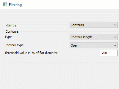
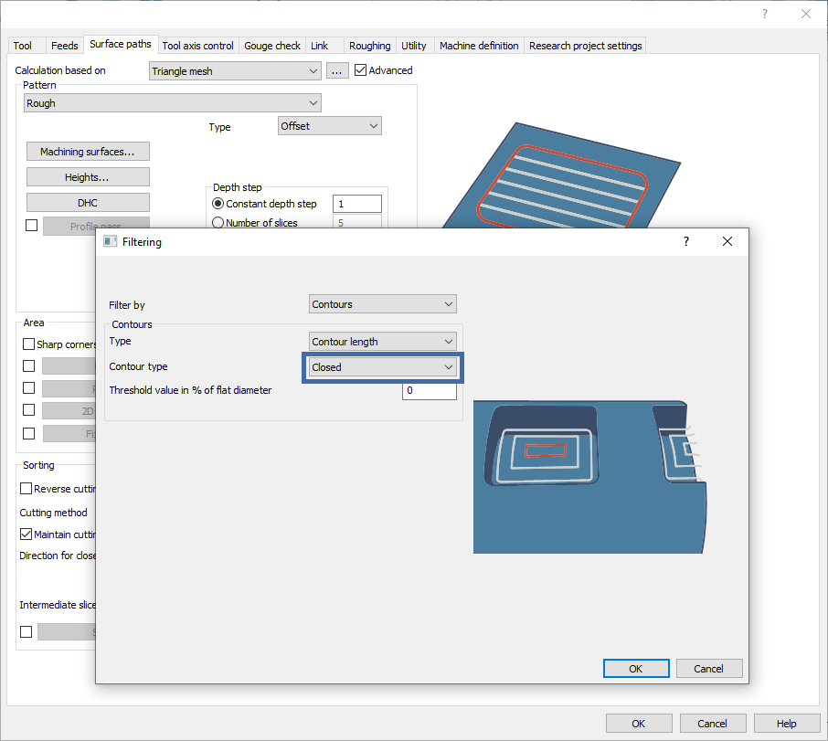
Independent Filter for Closed and Open Contours
A new, versatile feature has been added to the Advanced Roughing operation, allowing users to selectively filter Open, Closed, or both types of contours. Furthermore, users can now set a Contour length threshold, calculated as a percentage of the flat tool diameter, to filter out smaller contours. This threshold adapts for different shapes like Inscribed circles, Diagonal lengths, and Circumscribed circles, offering a tailored approach to contour selection. This functionality greatly enhances user control and flexibility in the machining process, enabling more precise and efficient operations.
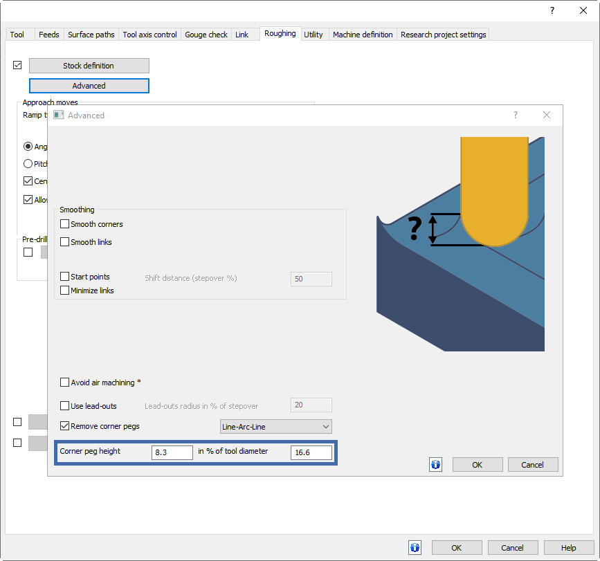
Corner Peg Height Control for Ball and Bull Mills
The Offset patterns in the Advanced Rough operation now boast a new feature for controlling the height of corner pegs and cusps when using ball and bull nose cutters. This innovative addition seamlessly integrates with the existing Remove corner pegs option, automatically managing step over and corner peg loop length. It offers users unprecedented precision and control in their roughing processes, making it a valuable tool for those seeking to achieve the highest level of accuracy and efficiency in their machining operations.

Smoothing Control for Offset Patterns
Offset patterns in the Advanced Rough operation have undergone a substantial improvement, particularly for intricate and detailed features. These patterns are now seamlessly smoothed, ensuring the preservation of the original last contour. This refinement significantly reduces abrupt changes in both acceleration and deceleration, thereby minimizing jerking motions during machining. The result is a consistent, high-speed roughing process that ensures smoother operations and superior efficiency, making it a crucial update for those aiming for top-quality machining performance.
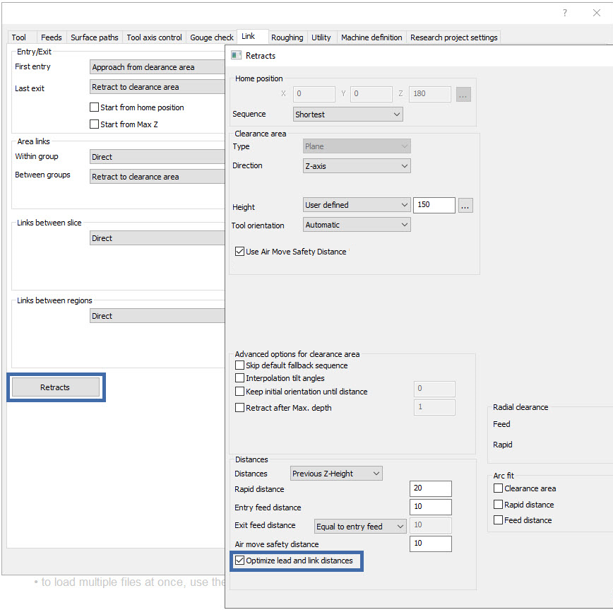
Optimized Link Height
The Advanced Rough operation introduces an enhanced in-process-stock awareness feature, specifically designed to optimize link heights and substantially reduce their occurrence: Optimize lead and link distances. This upgrade successfully reduces linking motions by up to 30%, translating to considerably shorter machining times while still adhering to machining safety standards. This development marks a significant stride in operational efficiency, offering smoother machining processes and a notable increase in productivity.


Optimized Ramp Height
Along with the link height, the new Optimize lead and link distances option, mentioned above, also does a fantastic job optimizing ramp heights! This enhancement is part of our improved in-process-stock awareness feature, which meticulously aligns ramp starts with the in-process stock height. This careful calibration significantly minimizes air cutting, leading to a reduction in overall machining time. Furthermore, it ensures an optimized entry into the material, enhancing the efficiency of the ramping process. This advancement in ramp height optimization is a key factor in achieving smoother operations and increased efficiency, offering users a more precise and effective machining experience.

Orthogonal Extension for Leads
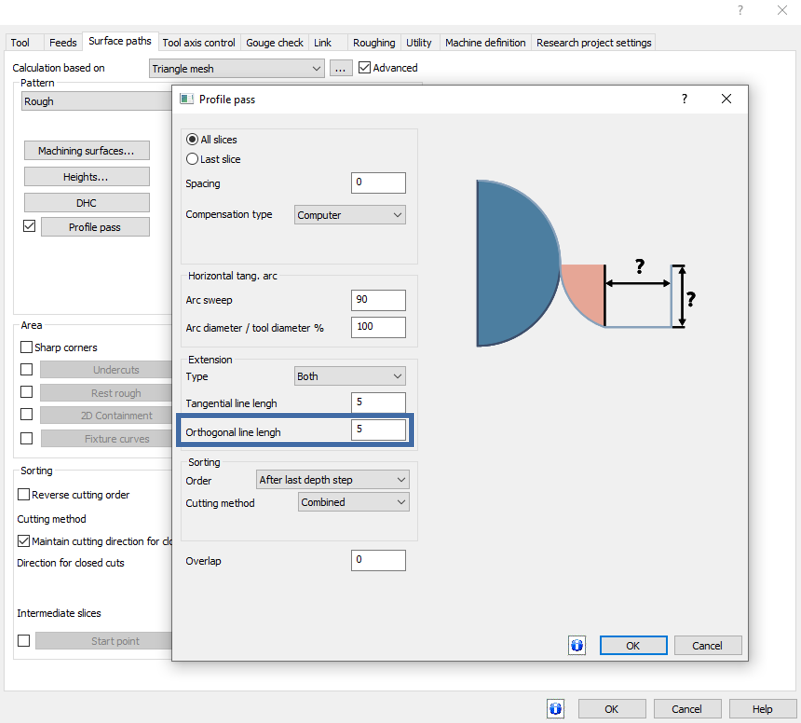
The latest update to the Advanced Rough operation introduces the orthogonal extension feature for profile passes. This enhancement complements the existing tangential extension for lead motions and is particularly beneficial when transitioning to CRC mode on CNC machines. The orthogonal extension minimizes the space required for this switch, proving especially useful in the machining of small pockets. This addition to the Advanced UI significantly increases efficiency and flexibility in machining operations, allowing for more precise and space-efficient movement during critical transitions in the machining process. This feature represents a notable advancement in the machining capabilities, providing users with an additional tool to optimize their operations.

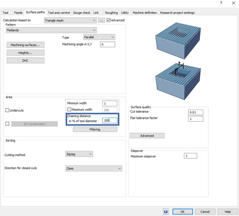
Flatlands
Ignore Gaps
The Flatlands operation has been upgraded with a game-changing functionality - the Ignore Gaps feature. Designed to maximize efficiency and productivity, this feature cleverly minimizes the number of retract and link motions, thereby ensuring a more continuous toolpath without unnecessary lifts. By strategically ignoring smaller gaps below a specified value, the toolpath becomes more compact, smoother, and significantly quicker in execution. This enhancement is a substantial leap forward for the Flatlands operation, leading to faster machining times and improved overall performance, making it a must-have for those seeking streamlined operations.

Advanced Planar
Advanced Planar Ordering Enhancement
The Advanced Planar operation has undergone a significant enhancement, particularly in its ordering process. The latest update introduces the application of the zig-zag cutting method to cuts that are divided by specified Fixture surfaces. This development is particularly noteworthy as it substantially reduces the number of retract links, thereby cutting down on overall machining time. The smoother, more efficient operation facilitated by this upgrade will greatly benefit users looking for a more streamlined and time-effective machining process.
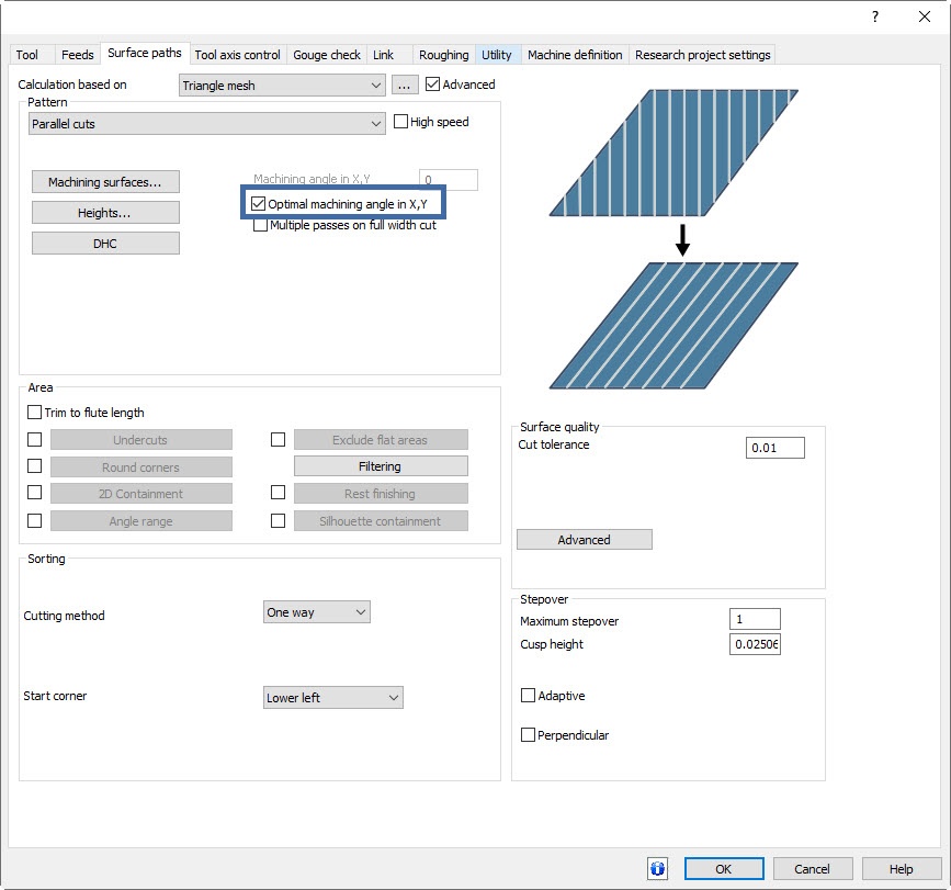
Optimal XY Angle
The Advanced Planar operation now features an exciting new option to optimize the XY angle for enhanced machining efficiency. This feature allows for independent angle adjustments across different regions, significantly improving material removal rates and surface quality. By aligning parallel passes with the longest dimension of each area, it ensures optimal machining conditions. This independent angle adjustment capability provides users with an opportunity to achieve the best possible results, marrying efficiency with precision in a unique and powerful way.
Pencil
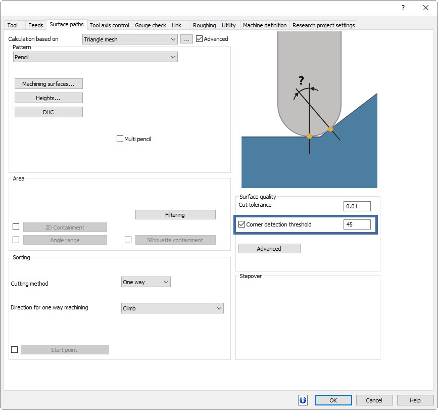
Corner Detection Threshold
The Pencil operation introduces a highly precise corner detection threshold feature. This innovative addition offers users greater control and precision by defining the maximum adjacent angle between adjoining faces. Consequently, the toolpath is not calculated for corners that exceed the specified angle threshold. By fine-tuning this threshold, users can tailor the toolpath to their specific needs, avoiding unnecessary machining on undesirable corners. This feature significantly boosts flexibility and efficiency, marking a step forward in the precision machining realm.
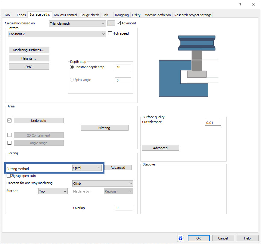
Advanced Z Level Finish
Spiral Machining for Undercuts
For users of the Advanced Z Level Finish operation, especially those working with undercut machining, there's exciting news: the introduction of a spiral ordering option. This new feature enables the generation of a spiral toolpath specifically for undercut machining, ensuring continuous and smooth machine motion. This advancement not only improves machining performance but also elevates the quality of the surface finish. This addition is particularly beneficial for complex machining tasks, offering users enhanced capabilities and superior results.

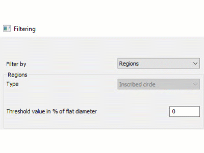
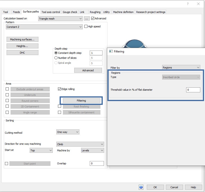
Advanced Filtering for Finishing
The finishing cycles of the Advanced Z Level Finish operation have been enriched with the addition of the Inscribed Circle filtering option. This new feature grants users an increased level of control over their machining operations by allowing them to filter out unnecessary toolpath segments. This enhancement is geared towards improving precision and efficiency in machining tasks. Users can now experience greater flexibility and a more optimized approach to their finishing operations, ensuring that only the necessary toolpath segments are machined for the best possible outcome.
Mill 3 Axis Premium
Deburring
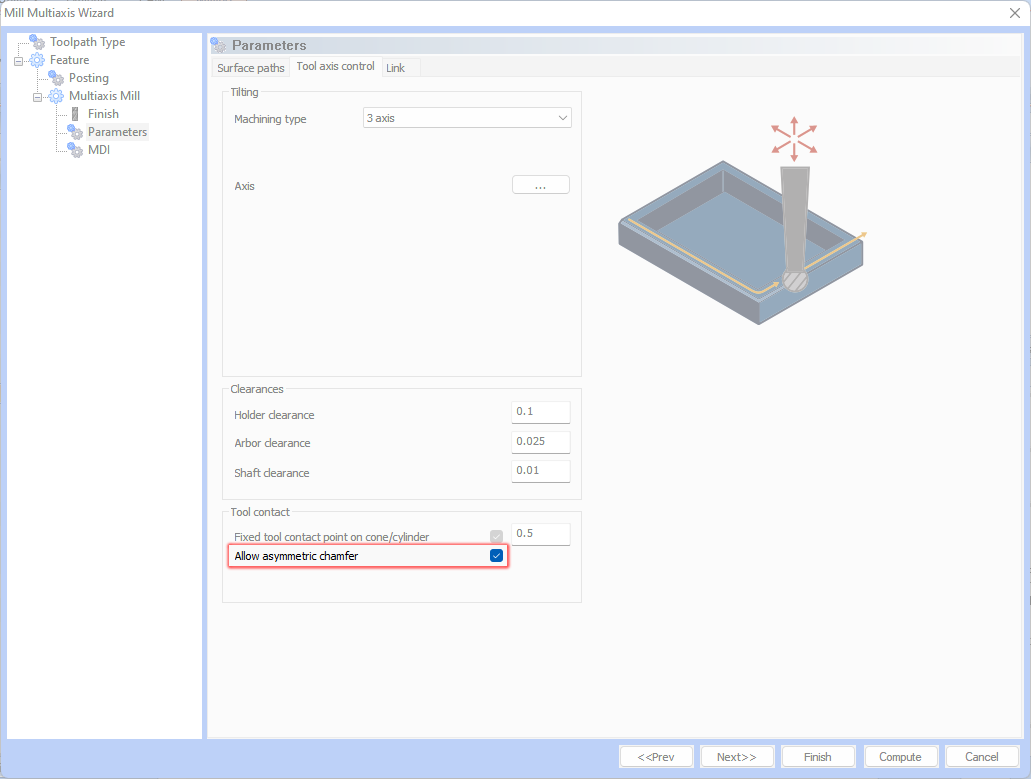
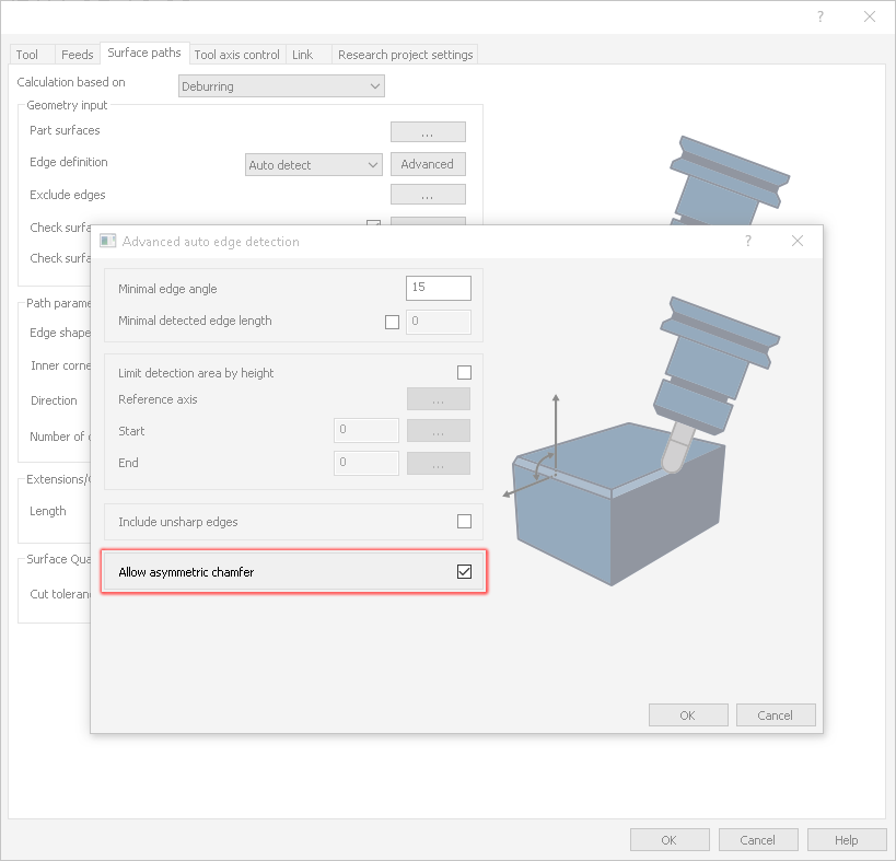
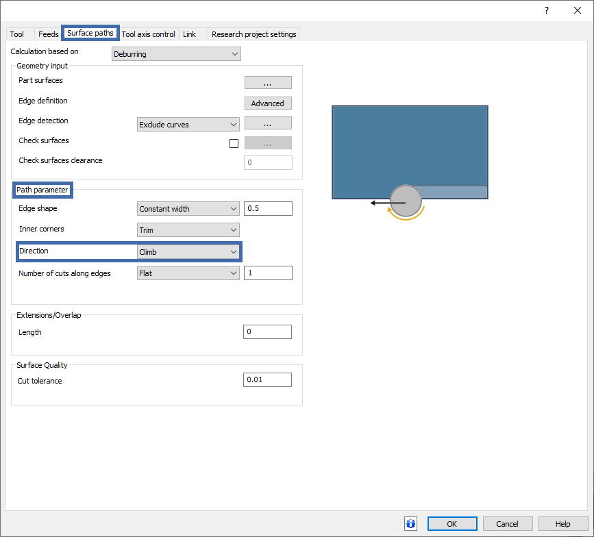
Allow Asymmetric Edge Shape
The Deburring operation just got a significant upgrade with the introduction of a new feature that allows the use of spherical mills for asymmetric deburring. This exciting development expands the scope of deburring operations, enabling more areas to be machined with precision and efficiency. Compatible with 3, 4, and 4+1 axis machining, this feature significantly enhances the ability to deburr more complex shapes while simultaneously reducing toolpath fragmentation. Users can now experience a heightened level of efficiency and precision in their deburring processes, making it a game-changing addition for those seeking to expand their machining capabilities.
Improved Order of Cuts
We are delighted to announce a notable improvement in the Deburring operation regarding the order of contours in climb/conventional machining using a shaft mill. This enhancement is specifically engineered to minimize the number of linking motions, thereby reducing overall machining time. The result is a smoother, more streamlined operation that enhances efficiency in the machining process. This update is particularly beneficial for those looking to optimize their contour machining strategy, ensuring more fluid and time-effective deburring operations.

Fixed contact point supports climb/conventional for 5-axis machining
There's great news for users of the Deburring operation, especially those working with 5-axis machining. A new feature has been introduced that significantly enhances deburring capabilities by allowing the use of a fixed contact point for Climb/Conventional directions in 5-axis deburring. This means that in Climb mode, the tool moves in the same direction as the spindle rotation, while in Conventional mode, it moves in the opposite direction. This advanced feature offers unprecedented flexibility and control in deburring operations, enabling users to achieve precise and efficient machining results. It's a significant leap forward for those seeking to maximize precision and efficiency in their 5-axis deburring tasks.

Surface Based
Along Tool Axis
A new lead type, Along tool axis, has been introduced. This option keeps the tool along the defined tool axis from the clearance plane to the start of the toolpath. This is the perfect lead when a straight line, to/from the toolpath with no unnecessary tool movement is required.

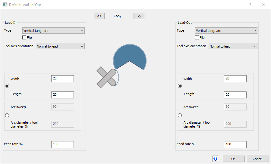
Normal to Lead
BobCAD-CAM V37 introduces Normal to lead tool orientation type for Vertical Tangent Arc Leads and Reverse Vertical Tangent Arc Leads. This option keeps the tool normal to the lead at all positions, enhancing precision and control and offering greater flexibility for any situation which may require it.

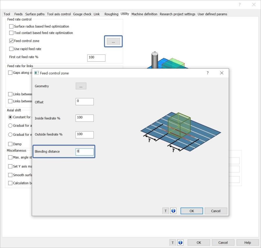
Feed Control Zone Blending
A new feature has been added to the Feed Control Zone dialog for surface-based machining in BobCAD-CAM V37. This option allows for controlling changes in the cutting feed rate when using the Feed control zone. When setting a specific feeds inside, and outside of a selected zone, the Blending distance allow you to set a distance along which the speed should gradually change between the two areas. This works to ensure smooth transitions and avoid abrupt accelerations and decelerations. The benefits include no dwelling and fewer tool marks on the surface, resulting in improved machining quality and efficiency.
Project Curves
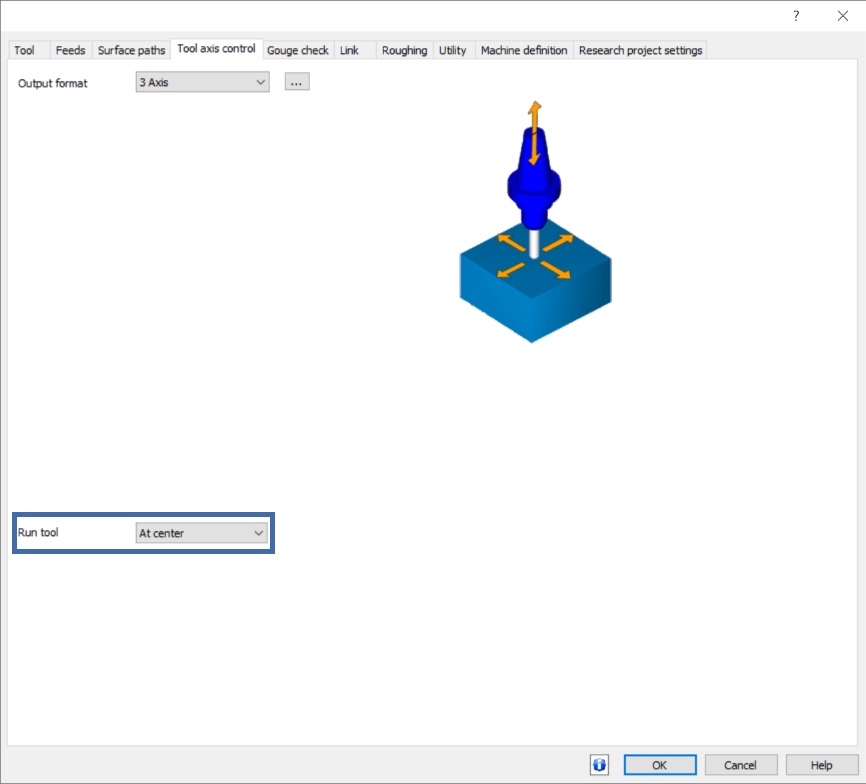
Run tool at
In BobCAD-CAM V37, a significant enhancement has been made to the Project Curves surface-based toolpath. Previously, users could specify a contact point on the tool only when the Cutting side was set to Center. Now, all contact point options (Auto, At center, At radius, At front, At user given point) are available regardless of the selected Cutting side (Left, Right, or Center). This flexibility is especially valuable on inclined surfaces, ensuring greater precision and control in toolpath operations.
Mill 4 Axis Pro
General
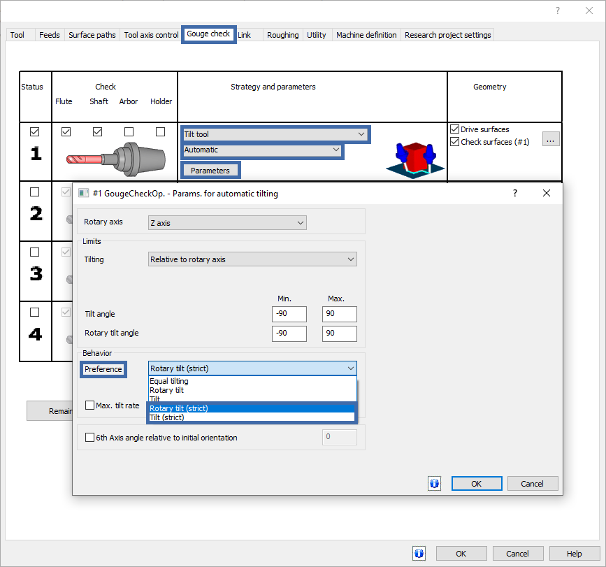
Strict Preference for Automatic Tilting
Strict Preference for Automatic Tilting: Users of the Automatic tilting gouge check strategy will be thrilled with the new feature that enhances collision avoidance. It restricts the degree of freedom to one, ensuring greater control and precision in machining operations. This feature maintains consistent table rotation based on input data, utilizing only the tilt axis for collision avoidance, which previously involved both rotation and tilting. This leads to smoother and more reliable operations.

Tool Orientation on Clearance
The Tool Orientation on Clearance feature is a significant addition that enhances the precision and safety of machining operations. This new capability allows users to set the orientation of the tool axis in relation to the normal of the clearance area. Such a feature ensures that the toolpath remains collision-free and predictable, without any unexpected changes in tool orientation that could compromise the machining process. Moreover, it includes an automatic selection option, where the system intelligently chooses the most suitable tool orientation based on the location and geometry of the toolpath. This enhancement not only improves the safety and reliability of machining operations but also offers increased convenience and efficiency, making it a crucial tool for complex machining tasks.
![]()
Restrict Links to Clearance Area
The introduction of the Restrict Links to Clearance Area feature marks a leap forward in machining precision and safety. This innovative feature ensures that all linking movements of the tool are confined within predefined clearance areas. In scenarios where it's not feasible to keep the link within these areas, a fallback mechanism, known as 'retract to clearance,' is activated. This approach ensures that the toolpath always remains within safe and predefined limits, effectively preventing any breaches of the machine's operating boundaries. The result is a significant enhancement in the safety and accuracy of the machining process, providing an extra layer of security and precision in complex machining tasks.
![]()
4 Axis Advanced Finish
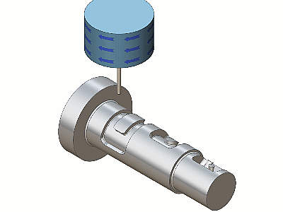
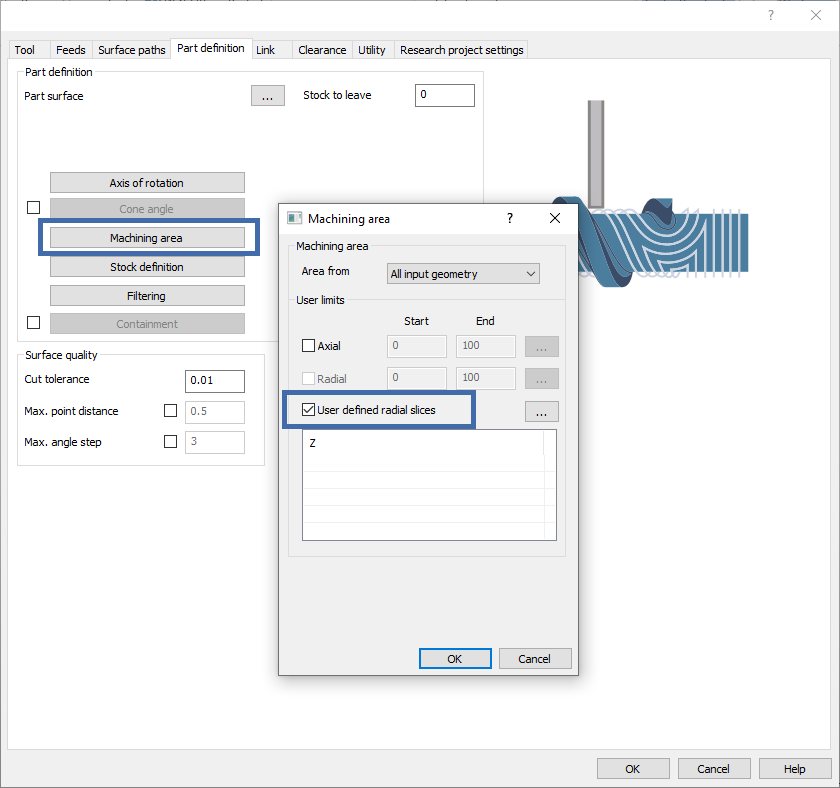
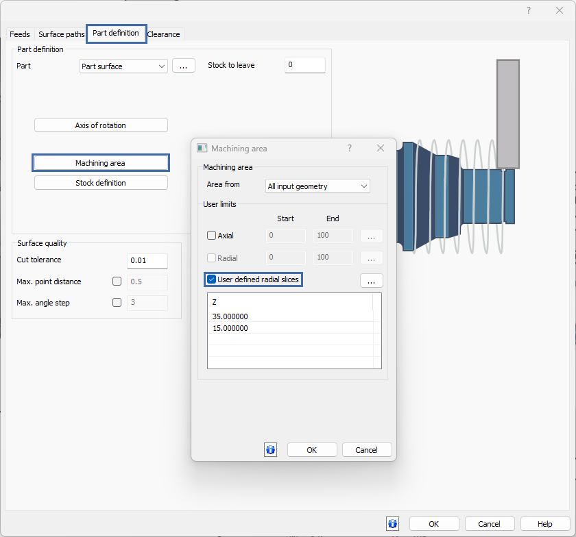
User Defined Radial Slices
The User Defined Radial Slices feature in Rotary Machining offers a high level of customization and precision. This enhancement allows users to define their own radial limits, tailoring the toolpath generation to focus only on specified radial sections. This level of customization is particularly advantageous when machining parts that require specific radial attention, as it ensures that the toolpaths are concentrated and efficient. The introduction of this feature eliminates the reliance on standard depth step definitions, offering more control and flexibility to users. This focused approach to toolpath generation is a significant step towards more efficient and precise rotary machining, catering to specialized and detailed machining needs.
Machine by Groups
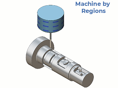
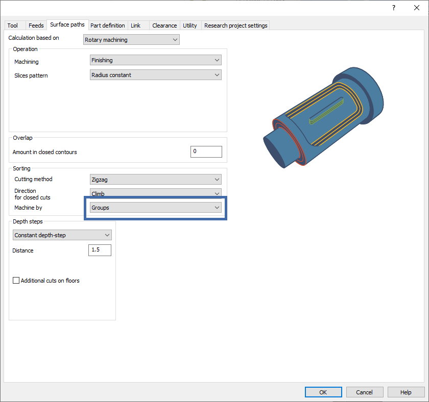
This feature brings a new dimension of efficiency to Rotary Machining. This advanced sorting method is an excellent addition to the existing options like 'Machine by Levels' and 'Regions.' It provides a more targeted approach to machining, where the sorting is based on specific groups or segments of the component. This method significantly reduces air cutting and unnecessary linking motions, especially in parts that require distinct machining strategies for different areas. By focusing the machining process on specific groups, it greatly enhances the overall efficiency of the operation, leading to faster and more precise machining. This feature is particularly beneficial for complex parts where different areas demand unique machining considerations, offering a more streamlined and effective approach to Rotary Machining.
Turn Mill
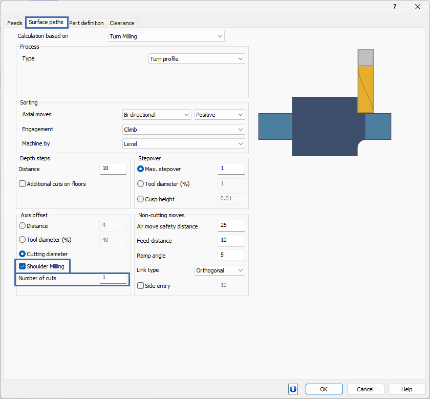
Additional Cuts on Floors
The Turn Milling operation sees a substantial enhancement with the introduction of the 'Additional Cuts on Floors' feature. This innovative functionality automatically identifies and corrects areas on floor surfaces where the depth of cuts does not align with the set parameters. By adding extra cuts, it ensures that the floors of cylindrical faces are machined thoroughly, leaving minimal or no uncut material. This feature is a game-changer, significantly reducing the need for additional operations to clean up these discrepancies. The result is a streamlined process that not only saves time but also enhances the precision and quality of the finished product, making it a valuable tool for any turn milling operation.
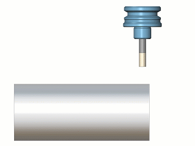
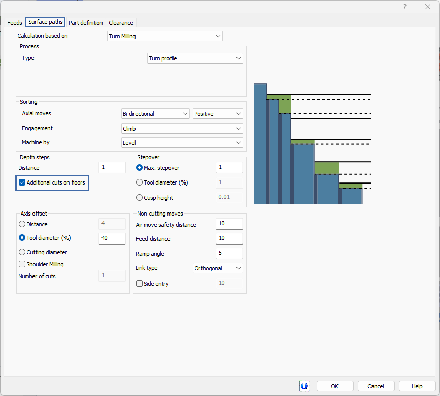
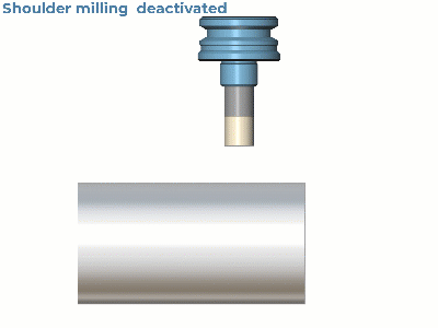
Shoulder Milling
The new Shoulder Milling feature in Turn Milling brings a significant upgrade to the machining of intricate features. Specifically designed to address the finishing of corners created by the Tool Axis Offset, this feature adds an extra layer of precision. It works by either adding extra passes without Tool Axis Offset or by gradually shifting towards the center if multiple cuts are used. This allows for a more detailed and accurate machining of corners, enhancing the overall quality of the final product. However, it's important to note that this method is not suitable for tools with a corner radius, as these tools will invariably leave a corner unfinishable by the same tool. This addition marks a step forward in the versatility and precision of turn milling operations.
Radial Cuts
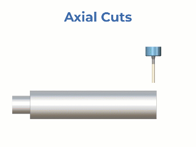
The introduction of the Radial Cuts option in Turn Milling is a revolutionary development that redefines the approach to cutting in this field. Moving away from the traditional spiral cuts made in the axial direction, this new method involves cutting slice-wise in the radial direction. This approach allows for each slice to be cut to its final depth before a sidestep is applied to move to the next slice. This cutting strategy is particularly beneficial for machining deeply slotted parts, as it significantly enhances efficiency and accuracy. By focusing on each slice individually, the Radial Cuts method offers a more precise and effective way to handle complex turn milling tasks, leading to improved productivity and finer results.
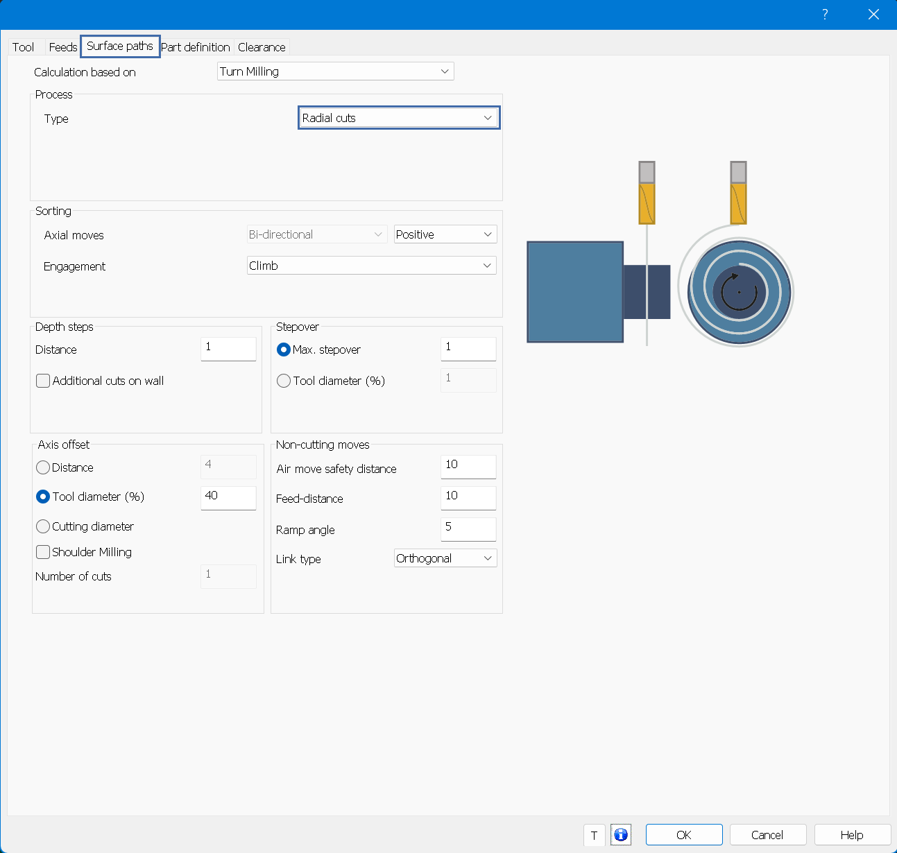
User Defined Radial Slices
The Turn Milling operation now includes a more flexible and precise feature - User Defined Radial Slices. This enhancement allows users to set their own radial limits, tailoring the toolpath generation to specific radii. Such customization enables a focused approach to machining, ensuring that the toolpath is precisely aligned with the unique requirements of each task. This feature is particularly useful when standard depth step definitions do not align with the specific needs of the job. By allowing users to define their own parameters, this feature opens up new possibilities for precision and efficiency in turn milling operations, providing a tailored solution that can adapt to a wide range of machining requirements.
Mill 5 Axis Pro
Surface Based
For Automatic Arc Leads With Automatic Tool Orientation and Barrel Tools
The Automatic arc lead option now allows you the ability to control the Tool axis orientation! The Automatic arc is a helpful tool, and for a while, the only thing lacking was the inability to control the orientation of the tool axis. In this new release, the Automatic arc option also allows you to control this with a Fixed, Tangential, or Tilted Tool axis orientation, to provide you with another level of control for an already powerful tool.

Multiaxis Machining
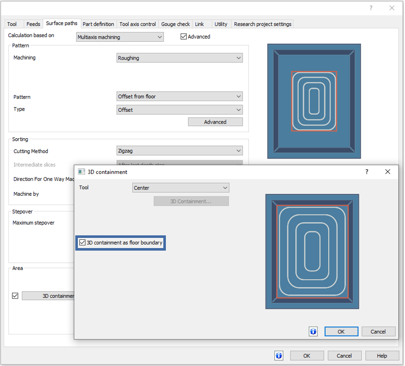
3D Containment as Floor Boundary
A significant development in Multi Axis Roughing is the introduction of the 3D Containment as Floor Boundary feature. This enhancement allows users to define 3D containment curves that act as boundaries for the floor surface, greatly streamlining the workflow. By reducing the need for manual input, this feature significantly boosts efficiency and precision, making the machining process smoother and more intuitive.

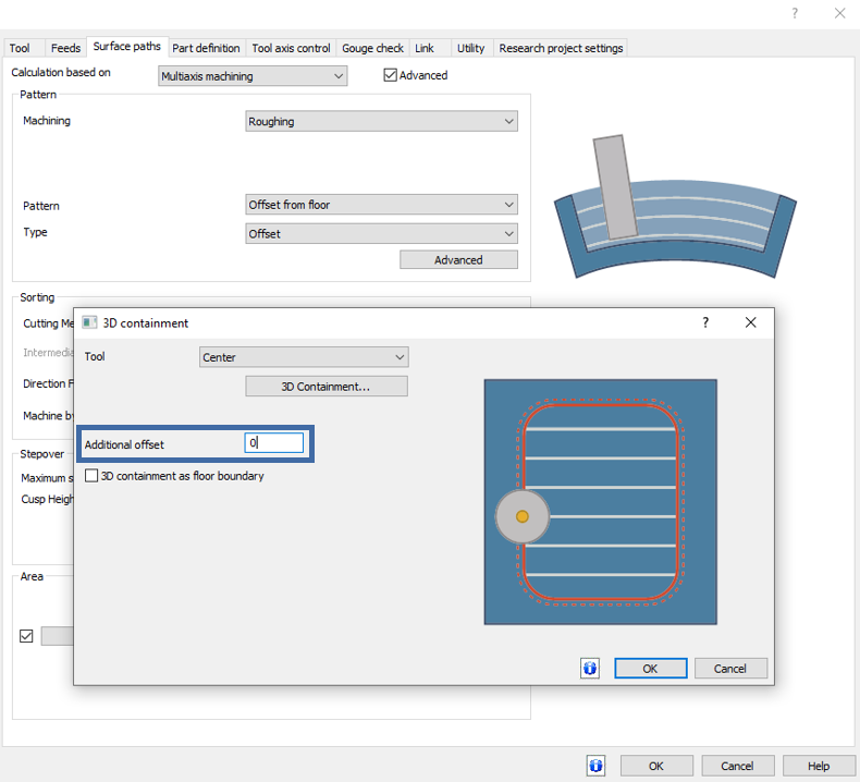
3D Containment Curve Offset
For users of Multi-axis Roughing, the new 3D Containment Curve Offset feature adds an extra layer of flexibility. This feature enables the definition of an additional offset to expand the machining area beyond the 3D containment curve. Notably, this is compatible with the Tool Center option and 3-axis machining, allowing for more versatility and precision in shaping and defining the machining area.

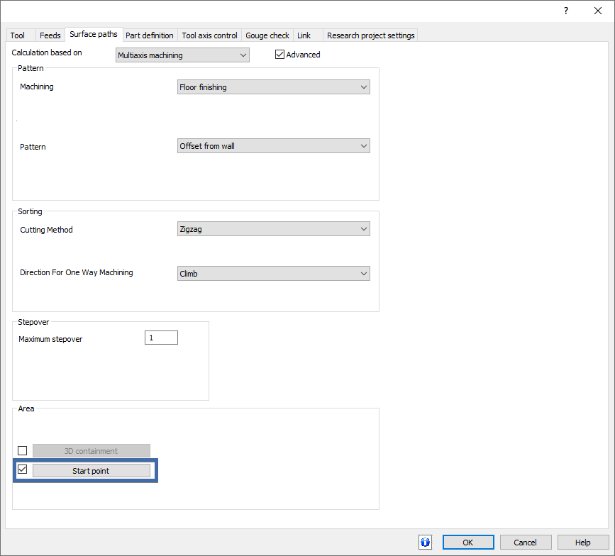
Start Point
The introduction of a user-defined start point in Multi Axis Finishing is a notable enhancement. This feature allows for greater control in finishing patterns, as it can be applied to all closed guide curves. When dealing with open drive curves, the start point aligns with one of the curve's endpoints. This addition offers increased flexibility and control over the finishing process, especially on single surfaces.

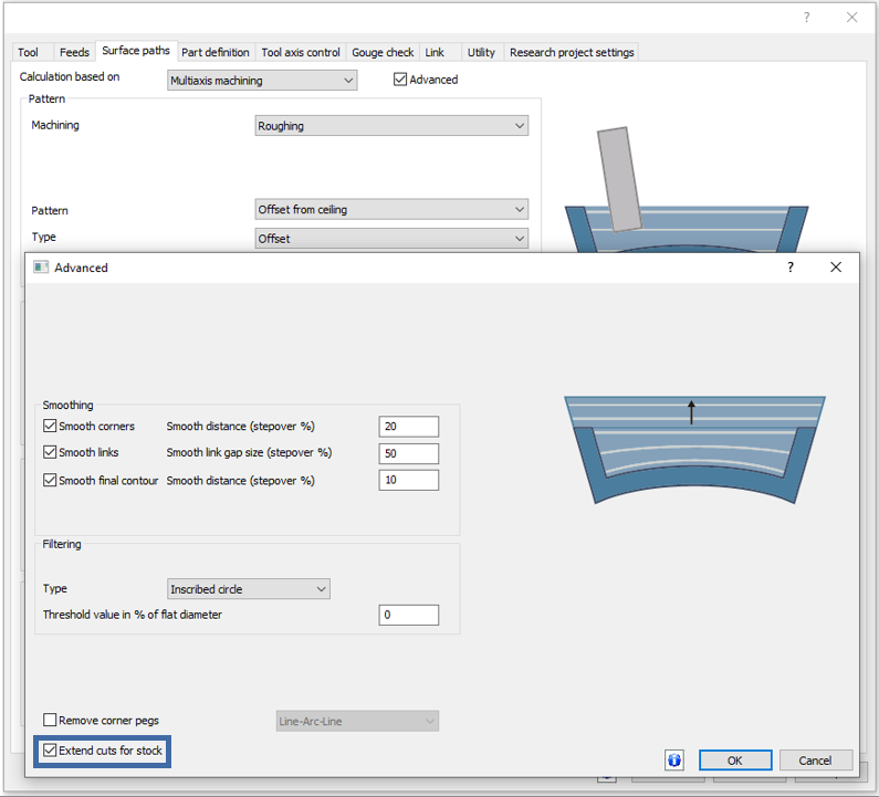
Extend Cuts for Stock
The new Extend Cuts for Stock feature for the Ceiling Offset tool marks a significant enhancement in versatility and precision. This option enables the extension of toolpath slices from the ceiling to the top of the stock, which is particularly beneficial when the stock's top surpasses the ceiling surface. Previously limited to the Morph between Ceiling and Floor pattern, this feature now broadens its applicability, offering more flexibility in machining operations.

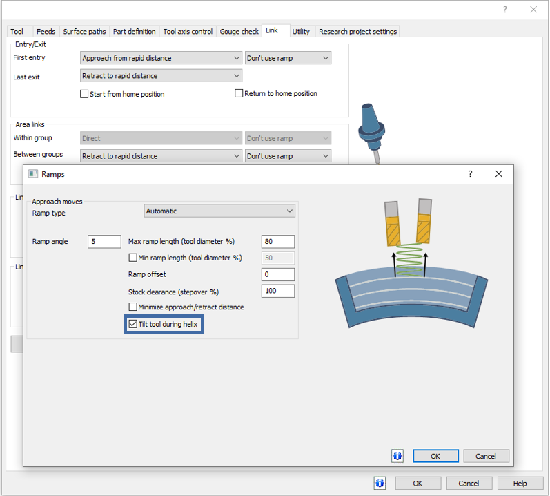
Tilt Tool During Helix
The Multi Axis Roughing Adaptive pattern now includes an innovative feature for tool orientation control - the ability to tilt the tool vector normal to the slice at every point on the helical ramp move. This enhancement reduces tool overloading and offers greater precision and efficiency, particularly beneficial in complex adaptive patterns.
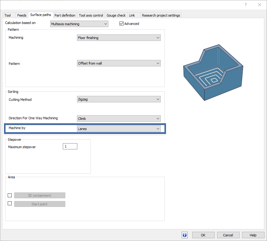
Sort by Regions/Lanes
The introduction of the Sort by Regions/Lanes feature in Multi Axis Machining Finishing is a significant step forward. This feature allows users to choose between sorting finishing cycles by lanes or regions, optimizing machining efficiency and reducing unnecessary linking movements. This sorting method is particularly advantageous when machining surfaces with multiple areas, providing the option to either treat different drive faces as one continuous region or machine each region successively for greater efficiency.

4 Axis Machining
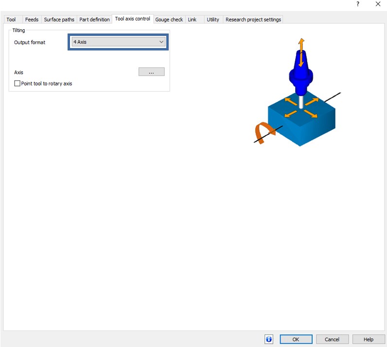
The latest update to the Roughing pattern of the Multiaxis Machining operation, 4 Axis Machining, brings a highly versatile feature that limits axis motions to three linear axes and one rotary axis. This is especially advantageous for machining centers that don't possess a third linear axis, as it allows for the application of rotary machining by setting the third linear axis normal to the center of rotation. This new functionality significantly broadens the scope of machining possibilities in the roughing process, offering greater flexibility and enabling users to tackle a wider range of complex shapes and designs with enhanced efficiency and precision.

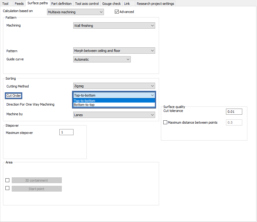
Select Cut Order of Wall Finishing
The Select Cut Order of Wall Finishing feature introduces a new level of customization to machining operations. Users now have the power to choose the sequence of their cuts – whether top-to-bottom or bottom-to-top. This option provides machinists with greater control over the machining process, allowing for strategic decision-making based on the specific requirements of the job. By selecting the most suitable cut order, users can optimize tool life, surface finish, and potentially reduce machining time, making this feature a valuable asset for achieving high-quality results in wall finishing.

User Defined Clearance Surface
The introduction of the User Defined Clearance Surface feature in Area Roughing marks a significant advancement in linking strategies. Users can now specify a custom surface that defines the clearance area for all retracts and pending linking motions. This increased level of customization ensures that the toolpath aligns precisely with user-defined parameters, offering enhanced control and precision in machining operations. It's a user-friendly and intuitive feature that extends the capabilities of clearance options, ensuring more accurate and efficient machining processes. However, it's important to note that this option is not available for output in the 4-axis format, making it a specialized tool for specific machining configurations.
![]()
Swarf
Select Tool Parts to avoid with Relink/Retract
SWARF machining introduces a new feature allowing users to specify which parts of the tool to check when using Avoid by Relinking or Retracting strategies. This enhancement offers a higher degree of control and customization, enabling more precise and efficient machining processes. It's a significant development for those seeking flexibility and optimization in SWARF machining capabilities.

Enhanced Tilting Strategies
SWARF machining's tilting strategies have received a substantial upgrade, powered by a new calculation kernel. These improved strategies ensure more consistent results, even in challenging scenarios, enhancing the reliability and precision of the machining operations. This advancement represents a major leap in the capabilities and accuracy of SWARF machining.

Mill 5 Axis Premium
3+2 Advanced Rough
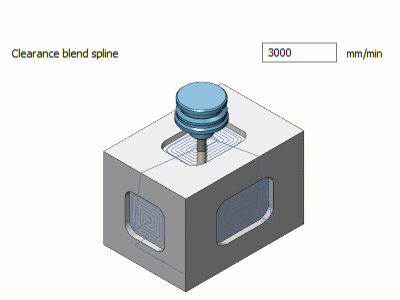
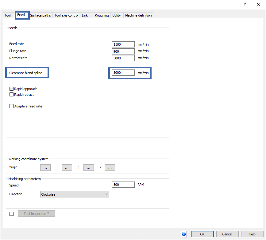
Clearance Blend Spline Feedrate for 3+2 Roughing
The 3+2 Advanced Rough operation introduces the Clearance Blend Spline Feedrate feature, offering unprecedented control over the speed during linking moves. This new functionality allows machinists to define the speed at which the tool retracts and approaches, especially when transitioning between different planes. This addition enhances the flexibility and precision of the 3+2 roughing process, ensuring smoother transitions and more accurate toolpath control.
Mill Turn
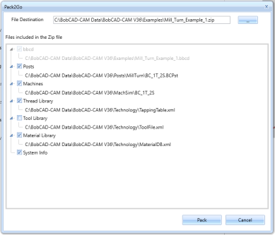
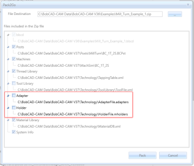
Enhanced Pack2Go
In BobCAD-CAM V37, we've improved the Pack2Go feature to include adapter libraries for Mill Turn jobs. When a Mill Turn job is present, the Technology\Adapters folder containing the necessary STLs and the AdapterFile.adapters file will now be included. This ensures all adapter files are backed up correctly. Additionally, users can back up all files in the data folder/backup folder with a new timestamped name by checking the backup checkbox in the UI.
| Previous Pack2Go Dialog | Current Pack2Go Dialog |
|
|
Simulation
Simulation Standard
Fixture Collision Detection
Fixture collision detection is now available for users who do not have the Simulation Pro module. This feature enables users to identify and avoid potential collisions between the tool and fixtures during the machining process, ensuring a safer and more efficient workflow. By providing this capability, BobCAD-CAM enhances the overall user experience, making it easier to detect and address fixture collisions!
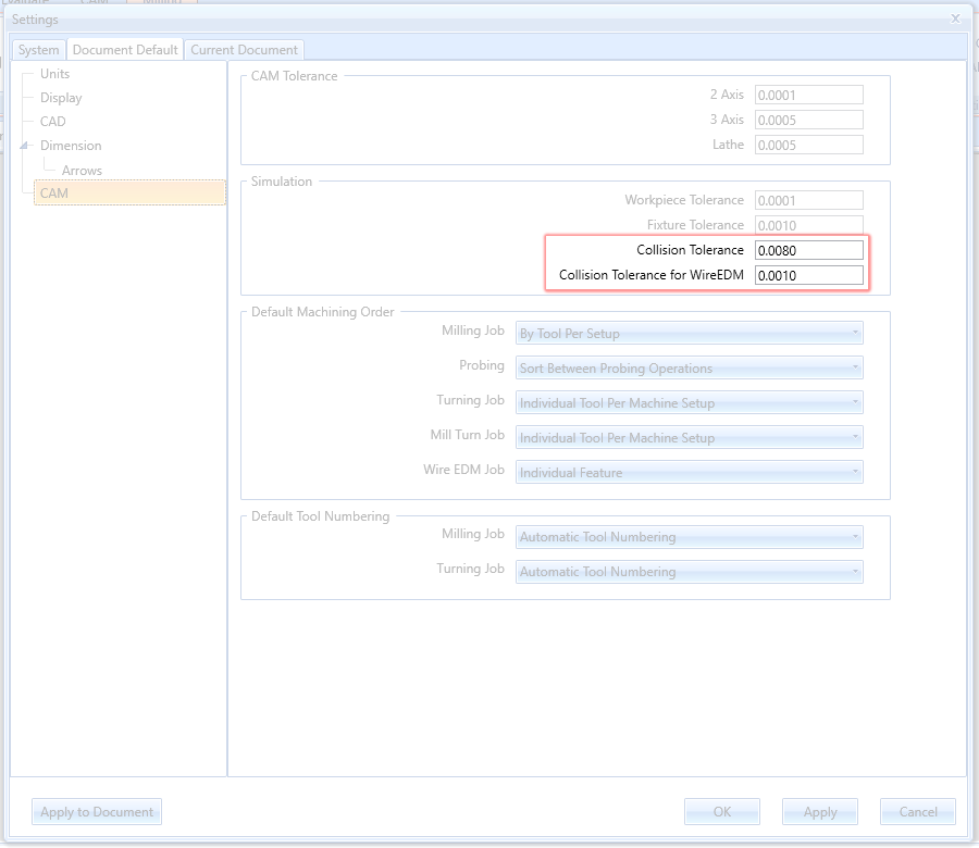
Update Collision Tolerance Value
In BobCAD-CAM V37, users can now input their own collision tolerance values in the simulation settings, offering greater control and precision. Previously, this tolerance was hardcoded, limiting flexibility. With this update, you can adjust the tolerance for deviation analysis, ensuring accurate simulations that match your specific requirements. This new feature can be found in the Document Default and Current Document settings, providing a more customizable and user-friendly experience for all job types, including WireEDM.
Posting
Support Local Subprogram Call (M97)
In BobCAD-CAM V37, support for local subprogram calls (M97) has been added, enhancing subprogram creation within the main file. Unlike M98, which calls subprograms in separate files, M97 allows subprograms directly within the main file. To enable this, new post variables have been introduced to generate sequence numbers for subprograms, similar to the variables used in lathe canned cycles. This improvement streamlines subprogram integration, ensuring more efficient and organized programming.
-
local_sub_num_call - Outputs a combination of a prefix, defined in post question 658, followed by the subprogram number, like "P100". This is particularly useful for setups that require a specific prefix for organizational or machine recognition purposes.
-
local_sub_num_def - Outputs the subprogram number prefixed by "N", such as "N100". This standard format aligns with common CNC programming practices, ensuring compatibility and ease of integration.
-
local_sub_num_no_prefix - Simply outputs the subprogram number, like "100", offering a clean and straightforward identifier free from any prefixes.
Haas Peck Tapping Support
In our latest software update, we've introduced Blocks 102 and 103, specifically tailored for Haas peck tapping cycles. These blocks are integral for operators using Haas CNC machines, as they precisely manage the peck tapping process by defining exact peck depths and tapping points, ensuring high accuracy and adapting to the unique requirements of Haas systems. This enhancement streamlines complex tapping operations, allowing for more efficient and precise control directly through the software’s posting engine.
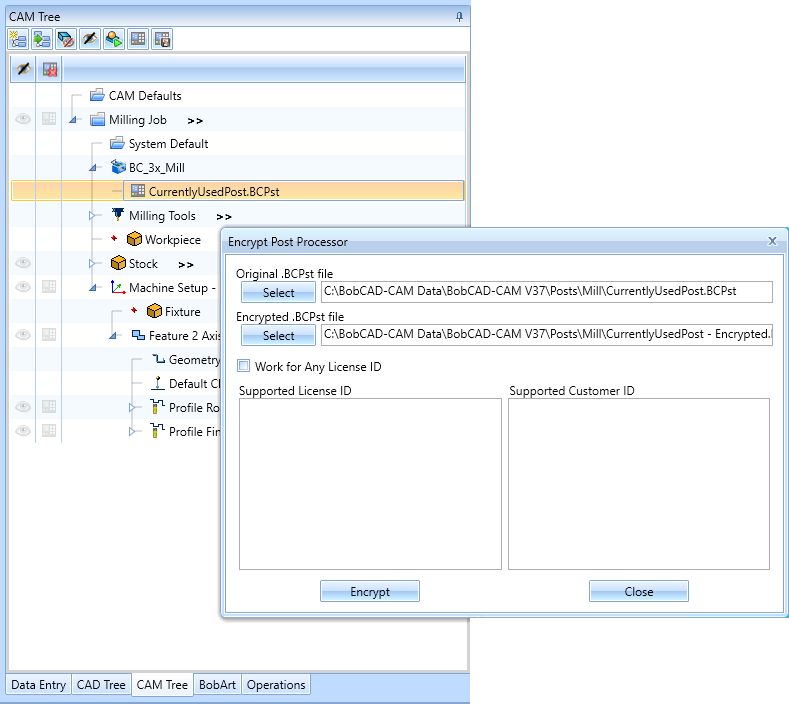
Post Encryption Dialog defaults
In this latest release, the Encrypt Post Processor dialog has been updated to automatically list the active post processor as the file to be encrypted. In the past, the same default post processor would be listed, which was rarely the post being encrypted. In this version we figured the least we could do is have it default to the post being used. Just another tweak to make your job a little easier!