


Bowling Sign Tutorial
Introduction
This tutorial is designed to help you become familiar with the BobART features.Follow this tutorial along with the other Emboss tutorials to learn more about the BobART Emboss features.The following features will be used to create the model:
- Emboss Swept - Add
- Emboss from Component - Merge High
- Emboss Regular - Merge Low
- Emboss Regular - Merge High
- Emboss Regular - Subtract
- Emboss 2 Rail Sweep - Merge High
- Loading an Image
- Vectorizing an Image
- Saving a Component
- Emboss from Component - Add
Example File
If you are connected to the Internet, the part file for this example can be downloaded automatically by clicking the following link: BowlingSignAssembly
Once you download and saved the zip file, extract the files on your system in an easy place to remember.You can then open the file to use with this tutorial. All files for the tutorials in this help system available for download can be found by clicking on the following link: http://www.bobcad.com/helpfiles.
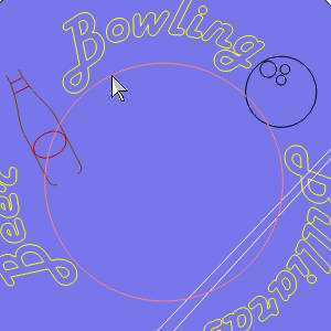
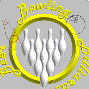
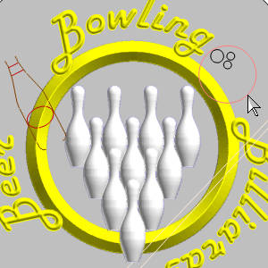
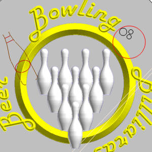
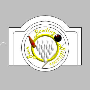
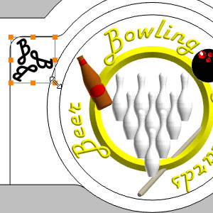
In the images below, you will see what we are working towards with our BobART creation steps.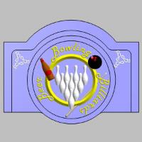


Part 1) Open the Example File
-
In the File menu, click Open.
The Open dialog box is displayed. -
Select the folder in which you saved the example files.
-
Select BowlingSignAssembly.sldasm, and click Open.
The file is opened and the geometry is displayed in the graphics area.
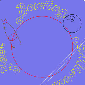
Part 2) Adjust the Visibility of the Model
In order to see the sketches we are building the BobART model from, we hide the MainBoard
-
The MainBoard is hidden.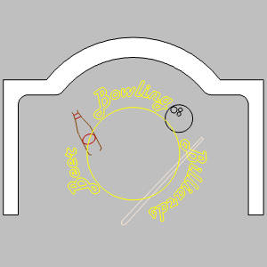
Part 3) Beginning an Emboss Model
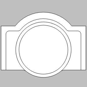
In order to create a feature, a coordinate system must be associated with the Emboss Model, and canvas must be set up.
Create the Canvas
-
In the
 BobART Manager tab, right-click
  Emboss Model, and click Edit Canvas.
The Canvas Definition dialog opens in the Data Entry Manager.
By default, the Canvas Definition dialog uses the
Set the Canvas Orientation
- In the UCS group,
Set the Canvas Size and Location
-
In the Origin group, set the X value to -
Important: From the Z0 of the selected UCS, the height of the center area of the MainBoard is
- In the Model Size group, set the Xvalue to 48.0000, and set the Y value to 30.0000.
Note: The resolution updates automatically as the size is updated. The Resolution will improve the quality of the model, but also increase the size of the file, and the amount of time it takes to regenerate the surface.
A portion of the emboss, which will created at the end of the tutorial is used to illustrate the point. The image on the left shows canvas with a resolution of 21, while the image on the right shows canvas with a resolution of 86.
Normally, since ultra fine details will not be visible on the final machined part, canvas with a higher resolution is not really needed. However, if it is wanted, wait until the model is complete and adjust the resolution at the end. This will keep regeneration times low during the creation of the model.
- Select the
 Remove Non-Emboss Area check box.
This option will remove all portions of the canvas that are not affected by an emboss feature.Those portions will, however, remain visible until the first time the canvas is regenerated, allowing you to confirm the proper size and placement of the canvas. - Clear the
 Make as Solid check box.
 -
Click OK.
-
Right-click
Emboss Model, and click Edit Canvas.
The Canvas Definition dialog opens in the Data Entry Manager. -
Update the Origin Z value to -1.5000.
-
Click OK.
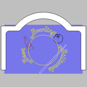
Part 4) Create the Ring
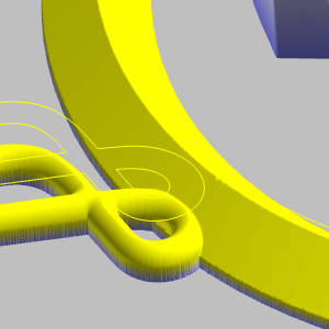
The ring that circles the bowling pins is created by using an Emboss Swept with the Add application type selected.
Create the Emboss Swept - Ring - Add
-
Right-click
Emboss Model, and select Emboss Swept
Set the Feature Attributes
-
In the Attribute group, change the Name to Ring.
- Click the drop down next to Color.
The quick access dialog appears. - Select yellow.
The quick access dialog disappears. - Leave the Application Type to Add.This will cause the emboss to be added to the canvas surface.
- In the graphics area, select the inner circle geometry as shown next.
The geometry is added to the Re/Select Geometry list. -
Click the drop down for Cross-Section and select Line.
- Set the Height value to 1.0000.
Leave the Slope Angle at 45.0000. - In the Fast Edit group, set the Base Height to
Since our canvas has been given a thickness equal to the outer edges of the Main Board, we just need to adjust the base height of our emboss features to the additional quarter inch of height in the center of the Main Board so our features are on, and not inside it. - Click OK.
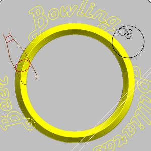
Notice the rest of the stock is gone leaving only the embossed area. This is because we have the Remove Non-Emboss Area check box in the Stock Parameters selected.
Part 5) Utilizing a Component - Bowling Pins
Using a component in BobART is really just importing an STL and adjusting its scale and position. In this case we utilize an STL of bowling pins setup in formation and use the Merge High application type.
Insert the Feature and Select the Component
-
Right-click
Emboss Model, and click Emboss from Component.
The Emboss from Component dialog appears. -
Change the Name to Pins.
- For the Color, select white.
- Under Application Type, change the type to Merge High.
- Click Load Component File.
The Open dialog appears. - Navigate to the folder in which you saved the example files, and select, BowlingPins.stl.
- Click Open.
The model appears in the graphics area.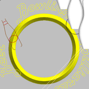
Set the Feature Parameters
- In the Origin group, change the values to:
X: =
Y: = -11.0000
Z: =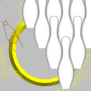
Important: While we have set the canvas itself further down in Z to leave our geometry visible, the component is positioned independently of the canvas position and would not be adjusted, as the rest of the features will, when we update the height position of our canvas at the end of the tutorial.Since it does no impede our ability to view the rest of the geometry needed for our remaining features, the component is placed at the height we intended it to be at completion.
- In the Component Size group, set the X Size to 13.0000.
The component is resized.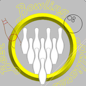
- Click OK.
The dialog disappears.
Part 6) Embossing the Text : Step 1
Since portions of the text overlap the ring we created, and since we would like the overlapping portion to stand out a little more, we do the text in two steps. In this step we use the Merge Low application type to take a bite out of the ring.
Insert the Feature and Set the Parameters
-
Right-click
Emboss Model, and click Emboss Regular. -
Change the Name to Words.
Yellow should still be the applied color. -
Set the Application Type to Merge Low.
-
Update the Cross-Section to Convex ARC.
-
Update the Radius to 0.5000.
- In the Fast Edit group, leave the Base Height at
- Click OK.
The effect will not be readily visible until you zoom into the intersection of the words and ring.
Zoom into the portions of the model where the capital B's overlap the ring, and notice the small notches we created on the ring emboss.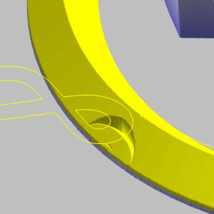
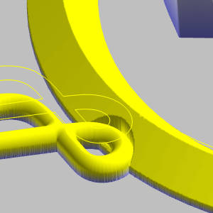
Part 7) Embossing the Text : Step 2
With the portions of the ring removed, we now repeat step 1 and replace the application type with Merge High.
- Repeat the steps of Part 6, but change the Application Type to Merge High.
With the Emboss Model regenerated, the view of the above area should now appear as seen in the image below.
Part 8) Suppress the Previous Feature
Suppressing features can be useful when create embossed models. In this case we want to test how the model would look without a certain feature.
- Right-click
 Words - Merge Low, and select Suppress/Unsuppress.
The name is grayed out. - Right-click
 Emboss Model, and click Regenerate.
The emboss model is updated.
For comparison, an image of the same feature is shown using the Merge Low on the left, and having it suppressed on the right.
Part 9) Unsuppress the Previous Feature
- Repeat the steps of Part 8 to return the model to its original state.
Part 10) Creating the Bowling Ball - Step 1
For the bowling ball, we use the same method as we did with the text. Step 1 will remove a portion of the ring with the Merge Low application type, and the following step will create the bowling ball with the Merge High application type. We use a convex arc with the same radius as the bowling ball.
Insert the Feature and Set the Parameters
-
Right-click
Emboss Model, and click Emboss Regular. -
Change the Name to Ball.
- Click Color,select black.
-
Set the Application Type to Merge Low.
-
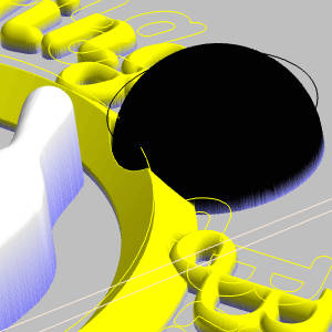
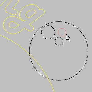
In the graphics area,select the geometry that represents the bowling ball as shown next.
-
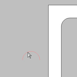
Leave the Cross Section set to Convex ARC, but set the Radius to 2.7500.
- In the Fast Edit group, set the Base Height to
- Click OK.
Part 11) Creating the Bowling Ball - Step 2
With the portions of the ring removed, we now repeat step 1 and replace the application type with Merge High.
- Repeat the steps in Part 10, but set the Application Type to Merge High.
With the Emboss Model regenerated, the Emboss Model show appear as seen below.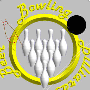
Part 12) Creating the Thumb Hole
For this, and the following feature, we use a custom cross section and the Subtract application type to remove material in order to create the holes in the bowling ball.
Insert the Feature and Set the Parameters
-
Right-click
Emboss Model, and click Emboss Regular. -
Change the Name to Thumb Hole.
- Set the color to red.
-
Set the Application Type to Subtract.
-
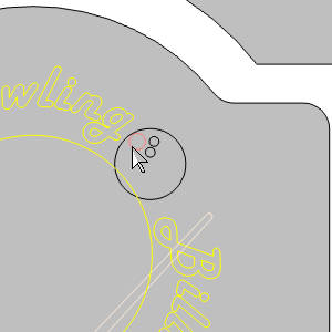
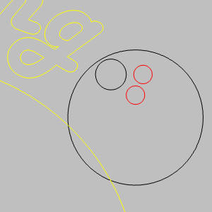
In the graphics area,select the geometry seen below.
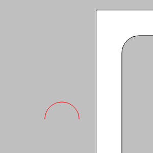
Note: The other two finger holes could actually be selected in this feature as well. In this tutorial we separate the like holes into two features so they can be handled differently if we so choose. Feel free to select all three holes at once. If you do, skip part 13 and move to part 14. ![]() at the top-right to hide the canvas while selecting geometry.
at the top-right to hide the canvas while selecting geometry.
-
Leave the Cross Section set to Convex Arc.
-
Leave the Base Height set to
- Click OK.

The hole is cut.
Part 13) Creating the Finger Holes
For this, and the following feature, we use a custom cross section and the Subtract application type to remove material in order to create the holes in the bowling ball.
Insert the Feature and Set the Parameters
-
Right-click
Emboss Model, and click Emboss Regular. -
Change the Name to Finger Holes.
- Set the color to red.
-
Leave the Application Type to Subtract.
-
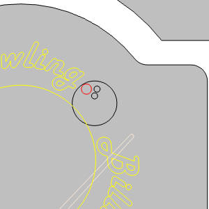
In the graphics area, select the geometry seen below.
-
Leave the Cross Section set to Convex Arc.
-
Leave the Base Height set to
-
Click OK.

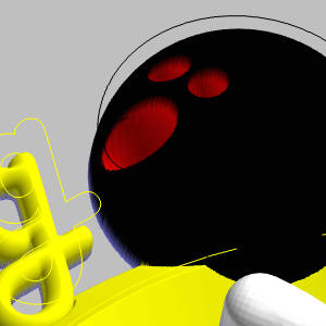
The holes are cut.
Part 14) Embossing the Cue
The cue is created with a 2 Rail Sweep and the Merge High application type will be used so that it goes through the ring.
Insert the Feature and Set the Parameters
-
Right-click
Emboss Model, and click Emboss 2 Rail Sweep.
The 2 Rail Sweep dialog appears. -
Change the Name to Cue.
- Click the Color drop down and select More Colors....
The Select Color dialog appears. - Set the RGB values to Red: 211, Green: 202, Blue: 171, and click OK.
-
Set the Application Type to Merge High.
Select the Geometry for Rail 1
-
By default the Selected Geometry list for Rail 1 has focus.
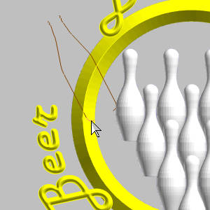
In the graphics area, select the geometry that represents one side of the cue as follows.
Tip: To reverse the chain direction, right-click the Rail Geometry (or Cross-Section Geometry) item, and click Reverse Direction.
Select the Geometry for Rail 2
-
Click in the Selected Geometry list for Rail 2.
-
In the graphics area,select the geometry that represents the other side of the cue as follows.

Select the Geometry for the Cross Section
-
Click in the Selected Geometry list for Cross-Section.
-
In the graphics area, select the geometry as follows.
- In the Fast Edit group, set the Base Height to
- Click OK.


Tip: Notice the image on the right, shows the cue with its components separated by realistic colors. This was done by splitting the geometry of the cue into separate 2 Rail Sweep features, one for each color. While this does not change the surface, and therefore does not change the final machined product, it can be a nice touch when presenting a visual representation of the final product to a customer.
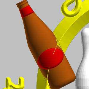
Part 15) Creating the Bottle
Just like the cue, the bottle is created with a 2 Rail Sweep, and the Merge High application type.
Insert the Feature and Set the Parameters
- Right-click Emboss Model, and click Emboss 2 Rail Sweep .
The 2 Rail Sweep dialog appears. - Change the Name to Bottle.
- For the Color,select brown.
- Leave the Application Type to Merge High.
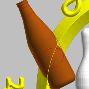
Select the Geometry for Rail 1
-
In the graphics area,select the geometry that represents one side of the bottle as follows.


Note: For this step, the Labels layer was hidden to make selection of our bottle geometry easily understandable. When a chain exists by itself, chain-selection can be done by simply holding shift and clicking the far end of the last/first entity.
Select the Geometry for Rail 2
-
Click in the Selected Geometry list of Rail 2 to give it focus.
-
In the graphics area,select the geometry that represents the other side of the bottle as follows.

Select the Geometry for the Cross Section
-
Click in the Selected Geometry list of Cross-Section to give it focus.
-
In the graphics area,select the geometry as follows.
- In the Fast Edit group, change the Base Height to 0.5000.
- Click OK.

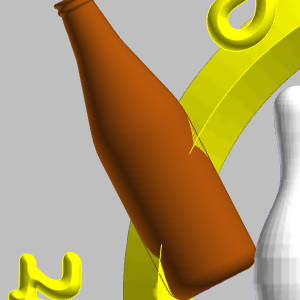
Tip: Notice the yellow ring is overlapping our bottle slightly, this can be prevented by first creating a Merge Low feature for our bottle, as we did with the lettering.Since this almost looks as if our ring is gripping our bottle, which is pretty cool, it will be left as is.
Part 16) Adding the Label to the Bottle
A simple emboss regular is used with the Add application type to add the material to the bottle where the labels would be.
Insert the Feature and Set the Parameters
-
Right-click
Emboss Model, and click Emboss Regular. -
Change the Name to Label.
- For the Color,select maroon.
-
Set the Application Type, to Add.
- In the graphics area, select the geometry for the labels on the bottle, as seen below.
The geometry is added to the Re/Select Geometry list. -
In the Cross Section group, leave Convex ARC as the selected cross section, but set the Radius to 0.2000.
-
Set the Base Height to 0.0000.
- Click OK.
Part 17) Adjust the Visibility of the Part
In this part, the Main Board is made visible again, and the sketches we used to create the emboss model are hidden.
-
-
In the
BobART Manager tab, right-click Emboss Model, and click Edit Canvas.
The Canvas Definition dialog opens in the Data Entry Manager. -
Update the Origin Z value to 0.5000.
-
Click OK.
Part 18 ) Load the Image
Now that the MainBoard is in Edit mode, we can import the image we will be vectorizing later in the tutorial.
- In the
 BobART Manager, right-click
  Images, and select Load Image.
The - Navigate to the location you saved the parts for the tutorial, and select 3B_Logo.jpeg.
- Click Open.
Under Images, a new item
  Image -3B_Logo is now available.
Part 19 ) Reposition the Image
We will now position and size the image to get it in a good location.
- Update the Origin Z value to 0.6000.
- Move your mouse over the location of the image, and notice your mouse switches to a pan icon.
Click and drag the image to the location shown in the following image.
- Once in position, hover over the bottom-right corner until the icon changes to scaling icon, then click and drag until it seems an even distance from the closest edges.
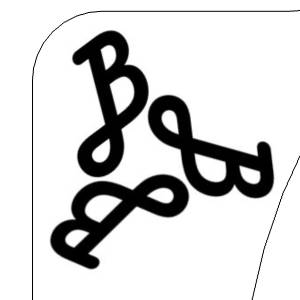
Notice each B in the logo is close to, but not touching, the edges of our parts. Because of the orientation of the logo we will also want to make sure the size we select will work on the other side of the sign as well. This can be done by dragging the image between the two corners to make sure it looks good in each location. As you can see, being able to see the image is extremely helpful. - For this example, set the width of the image to 7.0000.
Because the Keep Aspect Ratio option is active, the height updates automatically. - Update the Origin location to X-

- Click
 OK.
OK.
Part 20 ) Vectorize the Image
Vectorizing the image will provide us with the geometry needed to emboss the logo.
Vectorize the Image
- In the Layers Manager, create a new layer named Logo and set it as the active layer.
- In the BobART Manager, under Images, right-click Image -3B_Logo and select Vectorize....
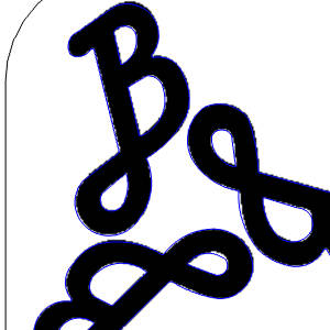
Tip: Notice we made the accuracy higher instead of lower.This is because the lower you go, the more the individual pixels are taken into consideration, as you can see in the image below.
Test Another Result
- Under Vectorize Parameters, click in the Accuracy: field and type *2 behind the existing value of 0.8000, and press Tab and click Apply.
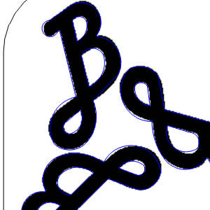
This result looks a little better than our last, so we'll try to increase the accuracy value once more.
Test Another Result
- Add *2 to the accuracy value, and press Apply.
Since this one isn't as good as the last one, we will change the value back.
Test Another Result
- Add /2 to the accuracy value.
- Click OK to exit the dialog.
- Right-click Image -3B_Logo and select Blank/Unblank.
The image disappears.
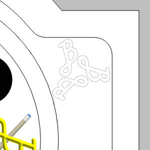
Part 21 ) Emboss the Logo
Now that we have the geometry we need from the vectorization, we can create an emboss feature for the logo with a basic Add application type.
Insert the Feature and Set the Parameters
-
Right-click
Emboss Model, and click Emboss Regular. -
Change the Name to Logo.
- For the Color,select white.
Leave the Application Type, on Add. -
In the Cross Section group, leave Convex ARC as the selected cross section, and the Radius as 0.2000.
- In the Fast Edit group, leave the Base Height at 0.0000.
- Click OK.
Part 22 ) Save the Logo as a Component
By saving this emboss as a component we can use it for the other side of our sign, and even for other projects in the future if we wish.
- Right-click Logo - Add, and select Save as Component/STL.
The STL Save Option dialog appears. - Leave the default tolerance, and make sure the Coordinate System is set to Local Art Model.
- Click OK.
The Save As dialog appears. - Select the folder the files are saved in, name the file LogoComponent, and click Save.
Part 23 ) Emboss from Component
With the component saved, we can now emboss from that component.
Insert the Feature and Select the Component
-
Right-click
Emboss Model, and click Emboss from Component.
The Emboss from Component dialog appears. - Change the Name to Right Logo.
-
Set the Color to white.
-
Leave the Application Type to Add.
-
Click Load Component File.
The Open dialog appears. - Navigate to, and select, LogoComponent.stl.
- Click Open.
The component opens in the graphics area but is hidden by the part geometry.
Set the Feature Parameters
- In the Origin group, change the values to : X:
- Click OK.
This concludes the tutorial.