


Emboss 2-Rail Sweep Example 2
Introduction
This tutorial explains how to make an Emboss 2-Rail Sweep using the Sync Rail Nodes option. A mirror frame is used to show the results created using the available 2-rail sweep options.
To use the Sync Rail Nodes option successfully, the two rails used for the sweep must have the same amount of entities.This is explained later in this tutorial. Complete this tutorial along with the other 2-Rail Sweep tutorials to gain a full understanding of the Emboss 2-Rail Sweep.
Example File
The part file for this example is available in the Examples\BobART\BobART Files folder, which can be located in the BobCAD-CAM Data folder.
Part 1) Open the Example File
-
Click File > Open.
The Open dialog is displayed. -
Navigate to
-
Select MirrorFrame.bbcd, and click Open.
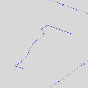
The prepared geometry displays in the graphics area as shown in the following images.The first image shows the two rails, and the second shows the cross section geometry.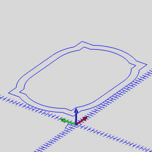
Part 2) Define the System, and Canvas
-
In the BobARTtree, right-click
 Emboss Model, and click Create/Modify Canvas.
The Canvas Definition dialog the appears. -
By default the UCS is set to
-
In the Stock Parameters dialog box, leave the Originvalues set to X0Y0Z0.
-
In the Canvas Size group, set the Xvalue to 38.00, and set the Y value to 26.00.
-
In the Material Appearance group, click the drop down arrow for Model Color.
The Model Color drop down appears. -
Select the Lilac color.
The Model Color drop down disappears. -
Click OK.
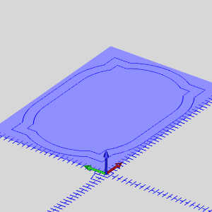
The defined canvas appears in the graphics area. -
Click Cancel.
The dialog closes.
Part 3) Add the Feature
-
In the BobARTtree, right-click
Emboss Model, and click Emboss 2-Rail Sweep.
The Emboss 2 Rail Sweep dialog appears. -
In the Material Appearance group, click the drop down arrow for Model Color.
The Model Color drop down appears. -
Select the Grey color.
The Model Color drop down disappears.
Part 4) Define the Rails and Cross Section Geometry and Generate Sweep
-
By default the Selected Geometry list in Rail 1 group has focus.
The geometry is added to the list, and the chain is added to the Profile Chain list.
This selects the entire outer loop and assigns a chain direction (shown with an arrow) for that loop.This is shown in the next image.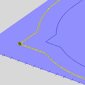
The geometry and chain direction for Rail 1 is now defined. -
Click in the Selected Geometry list in Rail 2 group to give it focus.
This time, select the inner geometry at the same location (top-left corner).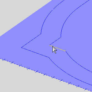
The results should look like the image shown next.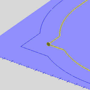
The geometry and chain direction for Rail 2 is now defined.Make sure that each Rail Geometry shares the same chain direction.
In addition, when using Sync Rail Nodes, the starting point for each rail must also be the same.That is, they must begin using the same entity as the other rail.(Both rails should already have the same start point because of the way that you selected the geometry.)
Tip: To show the selected chain and direction, click a Rail-Geometryitem in the BobART tree.To reverse the chain direction, right-click Rail Geometry, and click Reverse Direction.
Important: The location of the rail start points are critical to a good emboss.Make sure to keep the start points in the same location as seen in the image below.If the start points are not correct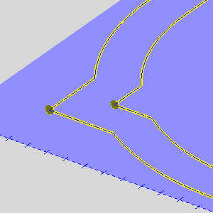
-
Click in the Selected Geometry list in Cross-Section group to give it focus.
-
Select the cross-section geometry.
The geometry and chain direction for Cross-Section 1 is now defined and should appear as follows.
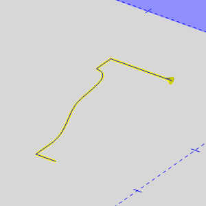
The direction of the selected cross-section geometry is important because the start point of the cross section is connected to Rail 1 and the end is connected to Rail 2.The cross section is swept along the rails from the starting point to the opposite end.The outcome of any 2-rail sweep is controlled entirely by the chain direction used for each entity.
The images below show the effect of the direction of the cross section.The images also show a cleaner result obtained using the Sync Rail Nodes option explained later in the tutorial.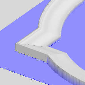
Tip: To show the selected chain and direction, click a Rail-Geometryitem in the BobART tree.To reverse the chain direction, right-click Rail Geometry, and click Reverse Direction.
-
Now that all geometry is defined, right-click
Emboss Model, and click Regenerate.
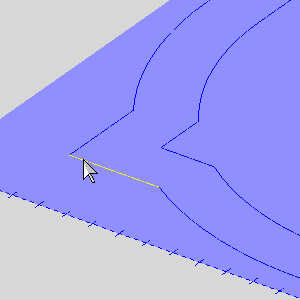
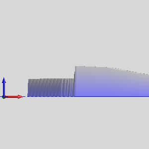
Examine the sweep in the corners of the frame.Notice that the cross-section geometry does not share all of the same nodes.This is the result of not using the Sync Rail Nodes option.The nodes are the points at the junction of different entities, such as lines to arcs.To create a more realistic looking frame, the cross section geometry should match up at these nodes on the inner and outer profile of the frame.If you rotate the view, you also notice that the frame does not have the same height, in the Z-axis, throughout its length.This is the result of using the Scale Cross Section Based on Width option and is shown next.
Part 5) Use Entity Summary to Find the Number of Entities
When using the Sync Rail Nodes option, the two rails must have the same number of entities.To find the number of entities contained in the rail geometry, follow these steps.
-
Click in the graphics areaand press E to hide the embossed stock.
-
In the document toolbar, click
 to enable selection mode.
Press and hold Shift, and click the outer geometry of the frame as shown next.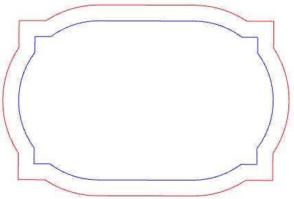
-
Right-click anywhere in the graphics area,and click Entity Summary.
In the Verify Summary dialog box near the top, the Selected Entitiesbox shows 16.
Click OK. -
Deselect the outer geometry (use chain-selection as explained previously).
Repeat steps 2-3 for the inner geometry of the frame.
The number of Selected Entities is also 16. -
Press Eto show the emboss.
Now that we know the inner and outer rails contain the same number of entities, we can successfully use the Sync Rail Nodes option.
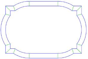
An image of the frame geometry, with green lines showing where the cross section is synced at each corresponding node, is shown next.
Part 6 ) Edit Feature and Regenerate the Sweep
-
Right-click
 2 Rail Sweep 1 - Add, and click Editto open the 2-Rail Sweep dialog box.
 -
Click to clear the
 Scale Cross Section Based on Widthcheck box.
This results in a uniform height around the rails using the dimension of the cross section geometry and is shown next.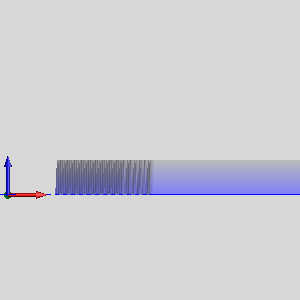
-
Click to select the
 Sync Rail Nodes check box, and click OK.
This results in a sweep that uses matching nodes at the end of each entity -
Right-click
Emboss Model, and click Regenerate.
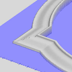
The before and after images are shown next.
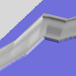
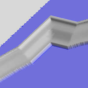
Notice the difference in the corners of this frame compared to the earlier frame.The Sync Rail Nodes option, for this example, helps to create a more realistic looking frame.For more information view Emboss 2 Rail Sweep.
This concludes the example.